 Kyle M. Hanquist*
 Iain D. Boyd
- Nonequilibrium Gas and Plasma Dynamics Laboratory, Department of Aerospace Engineering, University of Michigan, Ann Arbor, MI, United States
Electron transpiration cooling (ETC) is a proposed thermal management approach for the leading edges of hypersonic vehicles that utilizes thermionic emission to emit electrons to carry heat away from the surface. A modeling approach is presented for assessing ETC in a computational fluid dynamics (CFD) framework and is evaluated using previously completed experiments. The modeling approach presented includes developing boundary conditions to account for space-charge-limited emission to accurately determine the level of electron emission from the surface. The effectiveness of ETC for multiple test cases are investigated including sharp leading edges and blunt bodies. For each of these test cases, ETC affects the surface properties, most notably the surface temperature, suggesting that ETC occurs for bodies in thermally intense, ionized flows, no matter the shape of the leading edge. An approximate approach is also presented to assess ETC in an ionized flow and compares its cooling power to radiative cooling.
1. Introduction
The development of aeronautics has been largely driven by the passion to fly faster. From the flight of the Wright Flier that flew 48 km/h to the recent advances in hypersonic flight, most notably NASA's X-43A that flew at over 3 km/s, the velocity of flight has steadily increased. This trend is illustrated in Figure 1, which shows how flight speeds have increased during the first century of powered flight and how advances in flight technology (i.e., propulsion systems) have been generally associated with increased flight velocities. However, as these speeds reach hypersonic, contradicting aerothermodynamic design requirements present themselves. In order to maximize the range of any flight vehicle, the drag must be minimized, which essentially is designing a slender body with sharp leading edges for the case of hypersonic flight vehicles. This is shown by a theoretical analysis [1], which revealed the drag (D) is proportional to the leading edge radius (Rn),
where ρ∞ and u∞ are the freestream density and velocity; and k = 0 for a two-dimensional body and k = 1 for an axisymmetric body. However, this decrease in radius comes at a cost of increased convective heat transfer (qconv) as shown by a later theoretical analysis performed by Fay and Riddell [2] which shows that the stagnation point heat transfer is inversely proportional to the square-root of the vehicle leading edge radius,
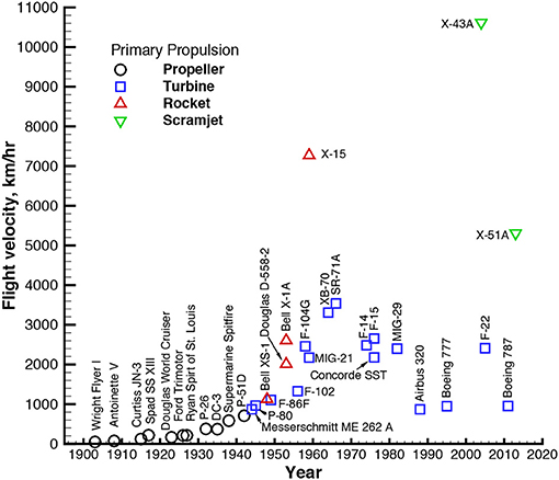
Figure 1. Typical flight velocities over the years.
Equations (1, 2) show that minimizing a property such as freestream density can reduce the drag while also lowering the convective heating, which is why hypersonic flight occurs at high altitudes. However, if the leading edge radius is reduced to limit the drag, there is a corresponding increase in convective heat transfer. Given that reducing the drag is generally one of the leading design criteria for flight combined with high flight speeds, high convective heating rates will be inherent and managing them will be vital. Currently, there are multiple approaches to manage the heat loads, which are discussed in detail in Glass [3]. One approach is to have a leading edge material able to withstand high-temperatures without degrading. One type of material that meets this criteria are ultra-high temperature composite (UHTC) materials, which were used on the NASA X-43 experimental hypersonic aircraft [4]. Since these materials can withstand high temperatures, the high convective heat rates are managed by radiative cooling, which is determined by the Stefan-Boltzmann law. Considering radiative cooling has a fourth power relation to the surface temperature, having a material that can withstand high surface temperatures is highly beneficial. Other modes of heat management include more of an active approach such as ablation. Ablation has significant heat management benefits through essentially a controlled thermo-chemical decomposition of the heat shield, which makes it an effective approach for re-entry flight. This shape change of the surface, while permitted for the blunt bodies of re-entry flight, is less acceptable for the sharp leading edges of hypersonic vehicles. An alternative approach that has been proposed involves using thermo-electric materials at the leading edges of hypersonic vehicles and is called Electron Transpiration Cooling (ETC) [5]. When exposed to high surface temperatures experienced during the extreme convective heating rates, these materials emit a current of electrons that may lead to a transpiration cooling effect of the surface of the vehicle [6]. This phenomenon is known as thermionic emission and occurs when the thermal energy given to the electrons is greater than the binding potential of the surface material [7, 8]. A recent numerical study was completed and showed that ETC can reduce the stagnation point surface temperature by 11 and 50% for 6 km/s and 8 km/s test cases, respectively, at 60 km altitude [9].
The purpose of this study is to determine the effectiveness of ETC for hypersonic vehicles and is done so by investigating a variety of test cases, including sharp and blunt body leading edges. In section 2 the modeling approach is presented for ETC, which includes the boundary conditions implemented and space-charge-limited emission effects. Emission for different types of surfaces (e.g., electrically floating and biased) is also discussed, as well as limiting cases for the emission. An assessment of the modeling approach is also included by comparing the modeling approach to a set of previously completed experiments in section 3 as well as a study of ETC for a sharp and blunt leading edges in a hypersonic flow environment. Finally, conclusions drawn from this study are presented and future work recommended.
2. Methods
The thermal state of the leading edge of a hypersonic vehicle is defined by its surface temperature and the heat transferred into the surface. Energy must be conserved so that at steady state the heat entering the surface must equal the heat flux leaving it. There are three physical sources that heat the vehicle surface: thermal conduction, mass diffusion, and radiation that combine to form aerodynamic heating. Thermal conduction, qcond, occurs when there are temperature gradients in the flow and is governed by Fourier's law of heat conduction,
where q is the heat transfer rate. There are also gradients of species concentration in the flow that lead to mass diffusion heat transfer, qdiff. The sum of mass diffusion and thermal conduction heat transfer will be referred to as convective heat transfer, qconv. Hypersonic flight is characterized by large temperature gradients in the flow that is most epitomized by a high-temperature gas flowing near a cool vehicle surface resulting in the high convective heating rates predicted by Equation (2). The heat flux away from the surface can either go into the flow or into the vehicle. The heat flux into the vehicle is called in-depth surface conduction, qin, and is also governed by Fourier's law of heat conduction, so it is driven by the temperature gradients in the material. Radiative cooling is typically the main form of heat transfer away from a hot surface,
where Tw is the surface temperature, ϵ is the material emissivity, and σsb is the Stefan-Boltzmann constant. The flowfield is assumed to be optically thin (i.e., transparent) so the heat from radiative cooling does not go into the flow but through it, which is an appropriate assumption for a sharp leading edge in a hypersonic flow [10].
The ETC process is another mode of heat transfer away from the surface and toward the flow. ETC can be viewed as an evaporation of electrons from the hot surface and is in some ways analogous to how evaporation of molecules from liquid results in a cooler surface. For a liquid molecule to evaporate, it requires energy (e.g., heat) that is supplied to the liquid surface, and if steady-state evaporation is to occur, it would require a source of heat provided to the liquid surface. ETC is similar in that if the surface is hot enough, electrons will be emitted. This phenomenon of converting heat into a current of electrons is called thermionic emission. The emitted electrons carry away energy from the vehicle surface determined by the electrons overcoming the potential barrier and the kinetic energy associated with the emitted electrons resulting in a heat flux of Richardson [11]:
where Je is the emission current density, kB is Boltzmann's constant, and e is the elementary charge. The work function, WF, is defined as the difference between the electrochemical potential of the electrons just inside the material surface and the electrostatic potential energy of an electron in a vacuum just outside the surface. This work adopts units of electron volt (eV) for the work function. Electrons are retained in the material surface and do work to overcome the potential barrier and escape the material, so the work function is essentially the minimum energy required to remove an electron from a material. A material with a lower work function would require less thermal energy for an electron to be emitted. Richardson also showed that when electrons escape the hot body, they carry with them an average kinetic energy of 2kBTw [12]. It is to be noted that the average kinetic energy of emitted electrons (2kBTw) is greater than the average kinetic energy of electrons in a unit volume at equilibrium (). The larger value arises from the fact that more rapidly moving particles occur more frequently in an emitted stream than in a volume at equilibrium, on average [12]. More details of the derivation of Equation (5) can be found in Richardson [11] and Herring and Nichols [7].
2.1. Modeling Approach
The numerical simulations of the fluid are performed using the CFD code LeMANS, which was developed at the University of Michigan for simulating hypersonic reacting flows [13]. LeMANS is a parallel, three-dimensional code that solves the Navier-Stokes equations on unstructured computational grids. LeMANS includes thermo-chemical non-equilibrium effects and the flow is modeled assuming that the continuum approximation is valid. The approach used for modeling ETC assumes that the translational and rotational energy modes can be described by a single temperature, Ttr, and that the vibrational and electron translational energy modes are described by an another single temperature, Tve. This assumes that the rotational mode is fully-excited, which is appropriate in this regime of flow [14, 15]. The CFD code is discussed in detail in Martin et al. [13] and Scalabrin [16].
2.2. Electron Emission
The electron current density is a function of the material's surface temperature and work function as determined by Richardson [11],
where AR is Richardson's constant which is assumed to equal 1.6 × 10⁶ A/m2/K2. This emission current density will be referred to as T-limited since the temperature of the surface is what limits the emission. It is to be noted that this current is only realized in ideal conditions: emitted electrons see no retarding electric field at the surface, are not reflected back to the surface through collisions with an external gas, nor see a virtual cathode created by space-charge limits. These space-charge limits are discussed in the following section.
ETC can be compared to radiative cooling using the ratio of heat flows away from the surface that is defined as,
and is plotted as a function of surface temperature and work function in Figure 2. When the ratio of ETC to radiative heat transfer (ι) is unity that means the surface is being cooled equally by ETC and radiative cooling. When ι > 1, that means ETC is a more effective cooling mechanism than radiation. The cooling power of ETC rises very quickly with temperature and is a more effective cooling mechanism than radiative cooling for lower work functions and higher surface temperatures. The heat transfer provided by ETC depends on the emission current from the surface, so it is important to accurately determine this current. Blackbody radiation (ϵ = 1) was assumed for the radiative cooling. It is to be noted that ETC does not replace radiative cooling but supplements it. The T-limited current is used in Figure 2, which assumes ideal emission conditions. Non-ideal conditions can limit the emission, which can lower the cooling power of ETC, and are discussed in section 2.3, but Figure 2 shows the high potential of cooling power provided by ETC and motivation to accurately determine the level of emission. Additional modeling is also included in the ETC framework including electric field effects, recombination of ions, and updated conservation equations which are discussed in detail in Hanquist [6].
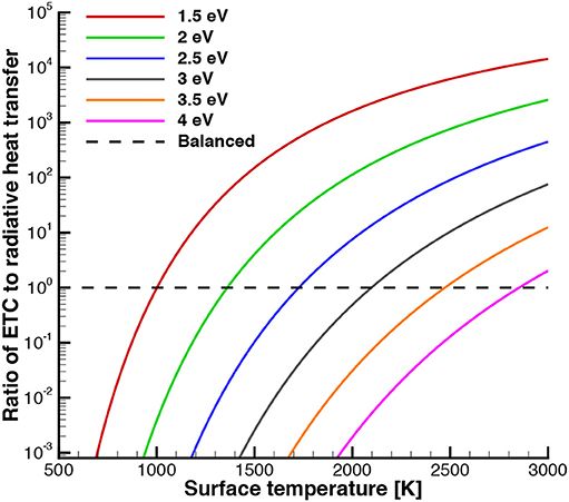
Figure 2. Ratio of ETC to radiative cooling effectiveness for various material work functions and surface temperatures where ETC is modeled using T-limited emission (i.e., Richardson current).
2.3. Space Charge Limit
A plasma sheath forms near the wall, which is a non-neutral region between the quasineutral flowfield and the wall. The sheath typically occurs because the electrons are much more mobile than the ions due to their mass difference. This higher mobility of electrons leads to more electrons leaving this region than ions, leaving the region positively charged, which generates a negative potential difference between the flowfield and the wall. Previous work showed that ETC is susceptible to space-charge limits in which a virtual cathode forms within the collisionless sheath pushing a portion of the electrons back to the surface before they escape into the hypersonic flow [9]. This effect can limit the level of emission from the surface resulting in smaller emission currents than predicted by the vacuum conditions of Equation (6). Emissive probes has been used for over 90 years to measure plasma properties (e.g., potential, temperature) and have been extensively studied [17]. Emissive probe theory was developed to relate measurable properties to desired plasma properties. Typically, the current was measured from the probe in order to determine the plasma potential and/or temperature. However for ETC, the plasma properties are known via CFD and the level of emission possible in these conditions is unknown.
2.3.1. Floating Surface
If the emissive surface is treated as an electrically floating surface (i.e., electrically insulated), the net current through the sheath must be zero:
where Ji, f and Je, f are the current density of flowfield ions and flowfield electrons through the sheath, respectively. Essentially, the amount of electrons that escape the sheath will be limited by the difference between the fluxes of flowfield ions and electrons reaching the sheath edge. Since the flowfield is quasineutral, the level of emission for treating the wall as an electrically floating surface is typically small. Typically, the net charge flow through the sheath edge is zero, so the boundary condition for plasma potential at the sheath edge will be a zero gradient. The wall potential can be approximated using relations provided by Hobbs and Wesson [18], which assume zero electric field at the surface:
where Γ is the ratio of the emission to flowfield electron current densities,
This approximation assumes that the ions arrive at the wall cold and the electrons are emitted with negligible energy. The flowfield electron current density can be calculated by,
where ne, f is the number density of flowfield electrons and ϕw is the potential of the surface. This approximation is good up to Γcrit in which a potential well forms such that a fraction of the emitted electrons return to the wall to maintain the current conservation in the sheath region. These critical values are space charge limited values [18],
The space-charge limited value can be also written as a function of the ion current density. Writing (Equation 8) in terms of Γ:
where Je,sc is the space-charge limited emission. The level of emission is limited by both the amount flowfield ions and electrons reaching the surface, essentially the level of emission in the flow as will be shown in section 3.
2.3.2. Biased Surface
If the surface is not floating electrically and is negatively biased, a net current is permissible through the sheath edge. A situation such as this would occur if the emitted electrons reattach downstream on the vehicle and travel back to the emitter surface completing the circuit as shown in the schematic in Figure 3. The electrons, denoted by the red dots, are emitted from the leading edge, which is susceptible to high surface temperatures due to its sharp radius, through thermionic emission and carries energy downstream where it deposits the energy as heat on the cooler aft-body of the vehicle. The red arrow denotes the electrical current being conducted back through the vehicle to the leading edge to complete the circuit. In practice, this could be achieved by having a battery in the circuit and within the vehicle to help drive the current. Electrons being emitted from the leading edge of a hypersonic vehicle (cathode) and reattaching downstream (anode) is analogous to a double emissive probe. The current work focuses on the leading edge (emitter region) and assumes that the surface can be biased relative to the quasineutral flow to a desired potential, whereas in reality the potential would be set based on the operating conditions. Similar to an electrically floating surface, this type of surface is also susceptible to space-charge limits.
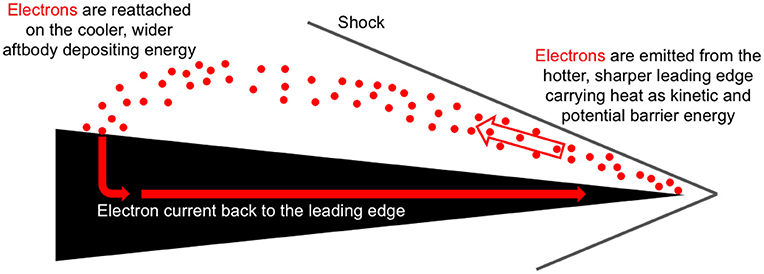
Figure 3. Electron Transpiration Cooling schematic. Reproduced from Hanquist et al. [9], with the permission of AIP Publishing.
Hara and Hanquist [19] derived an expression from Poisson's equation for space-charge limited emission for a biased surface that is similar to the work of Takamura et al. [20] but also accounts for kinetic effects and is written in a form that is more suitable for CFD implementation:
where
and the constants are defined as
where M originates from the Bohm criterion that requires the the ions to be accelerated up to speeds equal or greater than Mach 1. Typically this value is set to unity [21] and will be set to one in this work,
where Cs is the ion acoustic speed. τ is the ratio between primary and emitted electron temperatures and is predicted by the approach discussed in Hanquist et al. [9]. Equation (2.3.2) can be simplified by setting C = 0 because it quickly goes to zero for most cases of interest for ETC since [9] showed τ is greater than unity and a sheath potential larger than | −1| V is needed for ETC to be beneficial. Φw is the normalized sheath potential,
where ϕw is the voltage drop (i.e., sheath potential) between the surface and the plasma and Te is the electron temperature which is estimated using approach in Hanquist et al. [9]. The sheath potential can be expressed as the sum of the floating sheath potential, ϕfloating, and any additional applied bias, ϕapp:
According to Hobbs and Wesson [18], the normalized biased potential is –1.02 for a space-charge limited sheath so (Equation 18) can also be written as:
This theory has been compared to a 1-D Direct-Kinetic simulation and a good agreement is shown [19].
Past work on ETC [9] showed that the effectiveness of ETC in cooling the surface is directly correlated to the amount of emission from the surface as expected given (Equation 5). It is therefore useful to characterize what is the limit of emission from a biased surface. Equation (14) reaches a limit as the Φw approaches negative infinity,
Although high negative voltages may be difficult to realize or not ideal (e.g., arc discharges) in a hypersonic environment, this limit of the space-charge limited emission is still useful. For example, it can be used to to determine if the T-limited emission current densities predicted by Richardson in ideal conditions (Equation 6) can theoretically be obtained even if the surface could be biased significantly or if the emission will be space-charge limited no matter what the voltage bias of the surface is. The levels of space-charge limited emission are compared for each surface in Figure 4. Although the ratio of emitted electron to ion current density is strongly dependent on the mass of ion, the emitted current density is not because the ion mass cancels out when multiplied by the ion current density (Equation 17). As expected, the space-charge limited emission for a bias surface is much greater than an electrically floating surface.
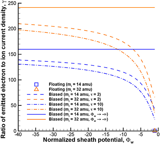
Figure 4. Space-charge limited emission analytic theory.
The modeling approach converges each case without emission (i.e., ETC turned off) and saves the ion number density at the surface, which is equal to the electron number density for cases without ETC due to charge neutrality. This ion number density is used in the sheath relations to determine if the emission will be space-charge limited when ETC is turned on. If the space-charge limited current, predicted by Equation (13) for a floating surface or Equation (14) for a biased surface, is less than the emission current predicted by T-limited emission (Equation 6) the emission is space-charge limited. More details of the plasma sheath modeling can be found in Hanquist [6] and Hanquist et al. [9].
3. Results
3.1. Assessment of Modeling Approach
Although using thermoelectric materials as a mechanism to reduce the thermal load on hypersonic vehicles is a recent approach, employing thermionic emission in high-speed flight is not a novel concept. In the 1960s there was interest to use thermoelectric materials on the nose of re-entry vehicles and collect the emitted electrons as a source of power generation [22, 23]. Experiments were performed using the plasma arc tunnel at the Sandia Corporation using a range of different flow conditions, emissive materials, and geometries [24]. These experiments were used to assess ETC previously although without plasma sheath effects accounts for [25] so this section focuses on comparing to the experimental data with the updated modeling approach given that previous work has shown plasma sheath effects can affect the level of emission significantly. The experiments of Touryan were performed in Sandia Corporation's plasma arc tunnels in the 1960s. A detailed description of the experiments is given in Touryan [22] and Touryan [24]. The experiments investigated the effect of different geometries, freestream conditions, and emissive materials on thermionic emission and the resulting power generation.
3.1.1. Test Case Description
The experiments investigated a diverse range of plasma generator shapes. However, results for only two of the geometries were reported, denoted S-6 and S-30. The S-30 geometry has a sharper nose radius but a larger emitter area. The S-6 geometry is an axisymmetric cone with a 0.73 cm leading nose radius, followed by a 10-degree-angle wedge, a cylinder region, and a 6-degree-angle wedge. The geometry is split into two regions, the emitter and the collector. The emitter region usually consists of a material with a lower work function than the collector region in order to promote the collecting surface to being more susceptible to electron recombination. This concept of electrons recombining on a collecting surface on the aft-body of the geometry will also be investigated for ETC as shown in the schematic in Figure 3, although modeling is reserved for future work. For conciseness, only the results for the S-30 geometry will be included in this work and a full comparison to the experiments can be found in Hanquist [6]. The S-30 geometry is an axisymmetric cone with a 1.0 mm leading nose radius, followed by a 13.5-degree-angle conical body. The whole geometry is considered the emitter region and has a surface area of 16 cm2. The material used for this geometry is tungsten. Flowfield meshes are generated for the geometry, and a grid convergence study revealed that the solution is grid-independent for these meshes. The computational grid used for the S-30 geometry is also axisymmetric and composed of approximately 28,000 cells, with 154 cells in the axial direction and 180 in the radial direction. The emissive material used for the S-30 geometries was tungsten. The experiments did not cite the material work function or emissivity, so a range of these properties are investigated (e.g., WF = 4.32, 4.48, 4.65 and ϵ = 0.30, 0.35, 0.40) similar to what was done in Hanquist [25]. It is to be noted that the work function is significantly higher than those studied in previous work focused on ETC applications (2–3 eV) [9]. Since both the material work function and emissivity have a wide range of possible values, this introduces a large uncertainty in the experiments, especially given how important these two parameters are to the cooling power of the material and resulting emission as will be shown. The material-specific correction factor for the Richardson constant is assumed to equal unity for each material. The experiments also examined the effect of different enthalpies and working fluids on thermionic emission and the resulting power generation. The freestream properties cited in the Touryan experiments for argon were a total enthalpy, ht, of 11.6 MJ/kg, pressure of 1010 Pa, and a Mach number ranging from 2.5 to 3 [22]. Previous work Hanquist [25] determined the temperature, velocity, and density, which is needed for the CFD code, from the listed Mach number, pressure, and total enthalpy and are provided in Table 1, where α is the level of ionization in the freestream.
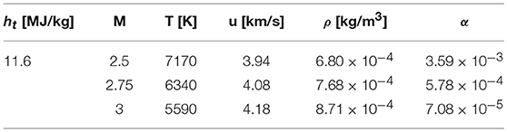
Table 1. Freestream properties of the Touryan experiment.
3.1.2. Surface Features
The surface temperature profiles along the test case body with and without ETC are shown in Figure 5A. Note that the normalized position is defined as the distance along the leading edge, s, divided by the leading nose radius, Rn. ETC is modeled both as assuming T-limited emission and also accounting for plasma sheath effects. Since the experiments noted that the emissive surface was electrically insulated, the emissive surface is modeled as electrically floating. The case shown in the figure is for the intermediate conditions (i.e., ϵ = 0.35, WF = 4.48 eV), so the specific trends for this case do not necessarily apply to all the other conditions. For each case, without ETC, the stagnation point temperature is between 5,100 and 5,300 K. When the ETC effects are modeled, the temperature near the stagnation point is greatly reduced for both T-Limited (i.e., emission is modeled assuming the level of emission is only limited by the surface temperature of the material, Equation 6) and SC-Limited (i.e., emission is modeled accounting for space-charge effects which can reduce the level of emission predicted by T-Limited), reducing the surface temperature by nearly 2000 K. Since the resulting temperature profiles are the same near the stagnation point for both T-Limited and SC-Limited ETC, this means the emission does not reach space-charge limits and a virtual cathode does not form in this region. Although space-charge limits are not reached near the stagnation point, farther along the leading edge the space-charge limits are reached and the temperature predicted by saturated ETC and ETC with plasma effects diverge. For this case, the stagnation point temperature is not the maximum surface temperature as has been shown in previous results. The reason why the further along the surface, the emission is space-charge limited is because there is less ionization in the flow reaching this region as shown in Figure 5B.
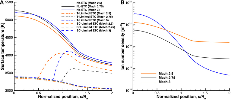
Figure 5. Surface profiles for the experimental case, (A) surface temperature, (B) ion number density.
3.1.3. Comparison to Experimental Data
The experiments measured the short-circuit currents from the emitter region, which are compared to the computational results in this section. The experiments cite a single value for the current from the emitter region and cited, under the best conditions of control, the repeatability of the experiments varied between 10 and 25%. For the S-30 geometry, which used tungsten as the emitter material, the results are presented in Table 2 for argon. If the emission is modeled assuming saturation current, the emission ranges from 2.62 A/cm2, for the Mach 2.5 case with a material work function of 4.65 eV and material emissivity of 0.40 to 9.93 A/cm2 for the Mach 3 case with a material work function of 4.32 eV and material emissivity of 0.3. These computational values are generally higher than the measured emitter current value of 3.3 A/cm2. However, if the emission is modeled accounting for plasma sheath effects, all the cases are affected by space-charge limits, reducing the emitter current. The space-charge limited current density ranges from 1.8 to 7.98 A/cm2, which agrees better with the experimental result of 3.3 A/cm2. It is to be noted that the largest Mach number no longer results in the highest level of emitter current as was the trend in previous cases [6]. The intermediate Mach number of 2.75 results in the highest levels of space-charge limited emission closely followed by the Mach 2.5 cases. The Mach 3 cases actually result in the lowest levels of emission, which is the opposite of the previous trend. This is due to the number density of ions at the surface as shown in Figure 5B. Although higher Mach numbers result in slightly higher ion number density at the stagnation point, the number density farther along the surface is significantly smaller than the lower Mach numbers. This leads to higher Mach numbers having slightly higher space-charge limited emission near the stagnation point, but markedly lower space-charge limited emission on the aft-body of the emissive surface due to the low level of ionization on the aft-body, which also contributes to the reported emitter current.
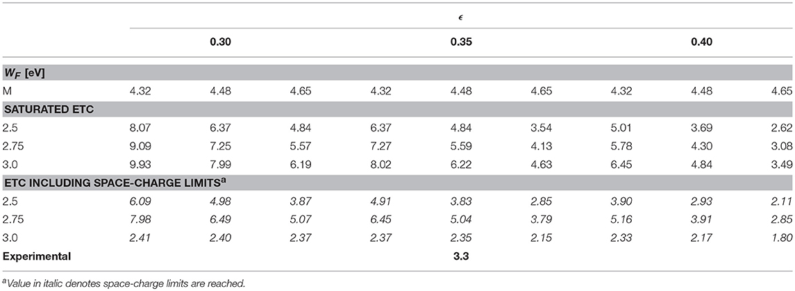
Table 2. Experimental vs. computational emitter current (A/cm2).
Generally, the computational results with plasma sheath effects accounted for bound the experimental data point quite well, especially given the number of uncertainties in the experiments. When the emission is assumed to be T-limited the computational results over-predict the experimental data point. But when space-charge effects are accounted for, the level of emission agrees better with the experimental value. Given the uncertainties in the freestream conditions (i.e., Mach number) and emissive surface properties (i.e., material work function and emissivity) of the experiments, the level of agreement obtained is considered satisfactory. The comparisons also provide motivation for new experiments to be performed and for further refinement of the computational models to better understand the potential benefits of ETC.
3.2. Sharp Leading Edges
3.2.1. Test Case Description
The geometry of this test case is based on the IRV-2 vehicle nose shape [26], where the nose radius is 1.905 cm with an 8.42° cone angle. This geometry is used because it is typical of a sharp leading edge for a hypersonic vehicle and computational grids have already been generated and verified in a previous study [27]. It should be noted that this test case is an axisymmetric cone whereas previous studies investigated a 2D planar wedge [9]. The freestream conditions investigated are at trajectory point 1 of the IRV-2 flight which corresponded to an altitude of 67 km, velocity of 6.78 km/s, and temperature of 227 K.
3.2.2. Surface Features
Given the importance of flowfield ionization on determining the space-charge limited emission, the convergence history of the ion number density is shown in Figure 6A. Typically, it is of interest to make sure the surface temperature is converged in order to make sure the test case is converged. As can be seen in the figure, the surface temperature is converged by the 10,000 iteration whereas the surface ion number density is mostly converged by the 25,000 iteration so this is the the ion number density profile used in the analytic sheath expressions. The residuals convergence history is shown in Figure 6B.
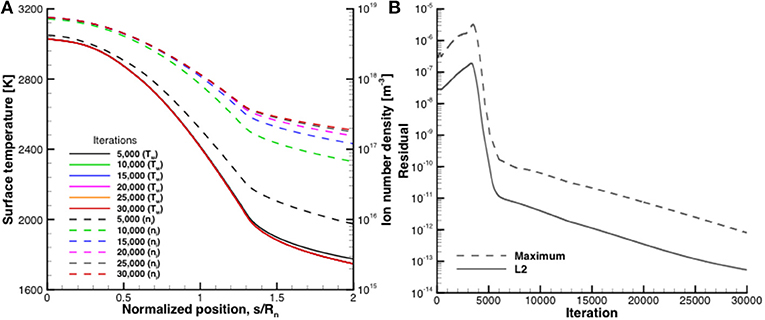
Figure 6. Convergence history of the IRV-2 test case without ETC, (A) surface temperature and ion number density, (B) computed residuals.
The surface temperature profiles for the test case with and without ETC for different types of emissive surfaces are provided in Figure 7. For the results with a floating emissive surface, Figure 7A, the surface temperature is reduced with ETC, especially for the T-Limited ETC case that assumed Richardson's current is obtainable. However, the emission is limited when ETC is modeled including plasma sheath effects resulting in smaller surface temperature reductions. Although each ETC with sheath effects case results in the same level of emission, the surface temperature is more reduced for higher work function values. This is because since case results in the same amount of space-charge-limited emission, the one with a higher worker function (i.e., binding potential) will result in more heat transfer from the surface given by Equation (5). This suggests that if space-charge limits are reached, minimizing the material work function is no longer necessary and can even be less beneficial to ETC. This suggests that there is an ideal work function where the T-limited emission predicted by Equation (6) equals space-charge limited emission that retains the highest possible work function to maximize qETC from the surface,
This is the material work function that would precisely result in the maximum amount of emission allowed by space-charge limits while also preserving an as large as possible potential barrier in the material for the electrons to overcome to maximize the cooling benefits. Essentially, if Je is limited in Equation (5), then the only way to increase the cooling power of ETC is to increase the work function. Although, as seen in Figure 7A, each of the work function values result in similar temperature profiles showing that it is less important to determine the material work function value if the emission is space-charge limited compared to when it is not (i.e., T-limited ETC).
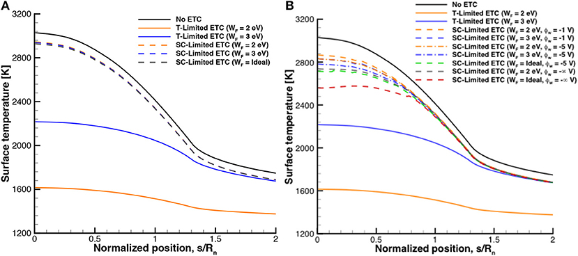
Figure 7. Surface temperature profiles for IRV-2 without and with ETC, (A) electrically floating surface, (B) negatively biased surface.
Figure 7B presents the results with a biased emissive surface and shows similar trends as the floating emissive surface case. Since the surface is biased, higher levels of emission are achievable allowing for greater reductions in surface temperature but each case is still space-charge limited. For the ETC cases with sheath effects modeled and a sheath potential of -1 V, the case with a higher work function results in a larger reduction in surface temperature. If the sheath potential is increased to -5 V, the surface temperature can be reduced even more for ETC. If the surface bias is increased to the limit provided by Equation (21), the surface temperature is reduced further and illustrates the ideal case of what cooling power of ETC can provide as the surface bias approaches negative infinity (ϕvc = −∞). While this is a special case, it illustrates what type of surface temperature reductions are obtainable with a large amount of bias. The case with both limited bias and ideal work function results in the lowest surface temperature of the cases with sheath effects accounted for. The space-charge limited emission with different work functions results in slightly larger reduction of the surface temperatures compared to the floating case, which is due to the biased case having a larger space-charge limited emission.
The ideal work function values are shown in Figure 8 for both the floating and biased surface types. For the floating case, a work function of nearly 5 eV would be most effective at cooling the surface near the stagnation point illustrating why the ideal work function case is more effective at cooling the surface than the 2 or 3 eV case in Figure 7A. For the biased cases, a work function closer to 4 eV would be most effective at cooling the surface and is lower than the floating case due to a less restrictive space-charge limit for current for a biased surface. While this work function is for an ideal case and only one trajectory point of the IRV-2 flight, it can help guide material development in deciding what value of work function will be most effective for ETC.
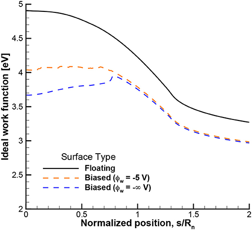
Figure 8. Ideal work function to maximize ETC cooling power for IRV-2.
3.3. Blunt Leading Edges
3.3.1. Test Case Description
It was shown in section 3.1 that accounting for ETC can result in different surface properties (i.e., temperature) than if ETC is not accounted for, even for surfaces with relatively high work functions and that are electrically floating. This shows that ETC may noticeably impact the surface temperature even for cases not specifically designed for ETC, and suggests that ETC should possibly be included in other modeling approaches of hot surfaces in an ionized atmosphere. Although the blunt shape does not present the same contradicting design requirements as a slender shape (i.e., drag is desired for a blunt shape) it is important to accurately model the thermal protection system environment to reduce uncertainty [28]. For this reason, a test case is selected with a blunt leading edge shape to determine if ETC can be present in non-sharp leading edge cases. The Stardust Return Capsule is chosen for this study due to the capsule's blunt shape (Rn = 23 cm) and high velocity of flight (12 km/s). One trajectory point is chosen for the study and the freestream properties are a velocity of 12.4 km/s, a temperature of 218 K, and density of 1.27 × 10⁻⁴ kg/m3 corresponding to an altitude of 81 km. More details of Stardust can be found in Olynick et al. [29].
3.3.2. Flowfield Features
The flowfield temperature contours are shown in Figure 9. The flow is characterized by a bow shock with a maximum temperature over 50,000 K along the stagnation line, which is significantly higher than the flowfield temperature in previous studies [9, 25]. The flowfield properties along the stagnation line are shown in Figure 10. Figure 10A illustrates the level of thermal nonequilibrium with the translational temperature peaking over 50,000 K while the vibrational temperature does not reach 15,000 K. The charged species number density is shown in Figure 10B. The number density reaches over 1021 m-3 at the surface suggesting that the surface will be susceptible to ETC.
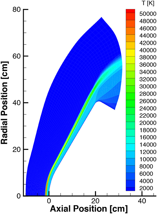
Figure 9. Temperature contours for Stardust case without ETC.
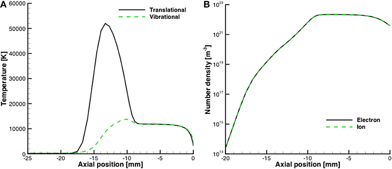
Figure 10. Flowfield properties along stagnation line for Stardust case, (A) temperature, (B) charged species number densities.
3.3.3. Surface Features
The surface profiles along the capsule surface are shown in Figure 11. High work function values are chosen for the test case since the work function value of Phenolic Impregnated Carbon Ablator (PICA), the ablative material used on Stardust heatshield, is uncharacterized although it is reasonable to assume it would be close to the graphite value in the previous section due to it's carbon base. For each work function value, the surface temperature is noticeably changed with inclusion of ETC modeling. The surface temperature is slightly increased for the 5 eV work function case which is due to the emitted electrons increasing the diffusive heat transfer [25]. For the 3 and 4 eV work function cases, the surface temperature is reduced noticeably compared to the case without ETC effects accounted for. For each of the ETC cases, space-charge limits are not reached which is shown by the sheath effects cases equaling the saturated ETC cases for each corresponding work function. Figure 11B shows that the heat transfer provided by ETC is comparable to the heat transfer away from the surface provided by radiation. For the 3 eV work function case, ETC provides more heat transfer from the surface than radiation. It is to be noted that this study is intended to investigate ETC for a blunt body and that some of the physics involved for the Stardust capsule (i.e., ablation and radiative heating) are not included in the modeling approach. This study showed that ETC can affect the surface properties even for a blunt body and suggests ETC should possibly be accounted for in future modeling approaches given the importance of accurately predicting the thermal protection system environment and response.
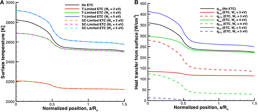
Figure 11. Surface profiles for Stardust case, (A) temperature, (B) heat transfer from the surface.
In order to estimate the degree in which ETC will be present, the theory for space-charge limited emission for a floating surface is utilized. Specifically, combining Equations (11, 12):
where the electron temperature can be approximated as the surface temperature,
where AETC is a constant given by,
This equation is beneficial as it allows the level of emission to be determined based on the surface temperature and the degree of ionization in the flow. It is to be noted that the emission is assumed to be space-charge limited. If the current provided by Richardson's equation (Equation 6) is less than this emission for a given work function, the current estimated by Equation (24) will not be realized. Using Equation (24) in Equation (5), the cooling power of ETC is compared to blackbody radiative cooling in Figure 12. For cases with low levels of ionization at the surface (e.g., ni < 1018 m-3), ETC is mostly negligible compared to radiative cooling. Whereas a case with a higher ionization level at the surface (e.g., ni = 1022 m-3), which occurs in the Stardust case, this study shows that ETC can be a comparable, or even dominant, mode of heat transfer from the surface compared to radiation motivating future work investigating ETC.
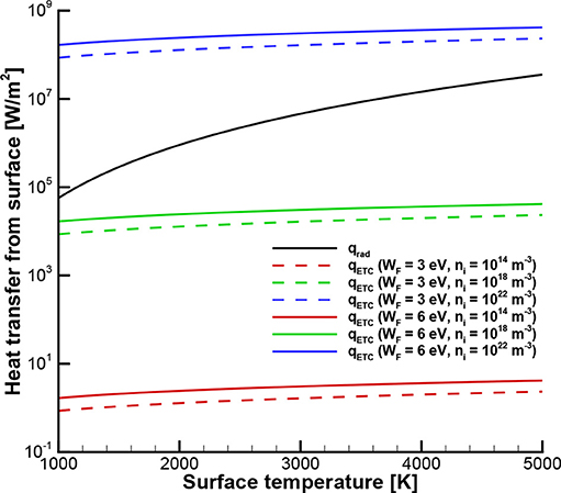
Figure 12. Comparison of radiative and ETC cooling rates.
4. Discussion
The goal of the present work was to assess the effectiveness of electron transpiration cooling (ETC) for hypersonic vehicles. A modeling approach for ETC in a hypersonic environment was presented that included plasma sheath effects as well as introducing an equation to determine the ideal work function. This modeling approach was assessed using experimental measurements that agreed reasonably well with the computational results given the degree of uncertainty in the experimental data. A test case with a sharp leading edge was studied showing that if emission is space-charge limited, a higher work function value will be more effective at cooling the surface. Finally, a test case was investigated with a blunt leading edge showing that ETC is still present for a blunt shape object in a thermally intense ionized flow showing the importance of modeling ETC in ionized flows. An approach for estimating ETC was also presented and compared to radiative cooling.
In order to continue to improve the modeling capabilities of ETC and to analyze its feasibility as a viable option for thermal management, the analysis has to not only look at the leading edge but also at a larger scale. This includes tracking the electrons in the flowfield back to the vehicle in order to ensure that the vehicle does not become charged. Also, new experiments are needed to continue to assess and validate the numerical approaches further, especially an investigation of how the emitted electrons behave in the boundary layer.
Data Availability
The raw data supporting the conclusions of this manuscript will be made available by the authors, without undue reservation, to any qualified researcher.
Author Contributions
All authors listed have made a substantial, direct and intellectual contribution to the work, and approved it for publication.
Conflict of Interest Statement
The authors declare that the research was conducted in the absence of any commercial or financial relationships that could be construed as a potential conflict of interest.
Acknowledgments
We thank Prof. Kentaro Hara of Texas A&M University for several useful discussions. This research was supported in part through computational resources and services provided by Advanced Research Computing at the University of Michigan in Ann Arbor. we gratefully acknowledge support for the initial portion of this work from the Lockheed Martin Corporation. In addition, we thank Luke Uribarri and Edward Allen of Lockheed for essential technical oversight. Portions of this work first appeared as a conference paper [30] and a doctoral thesis [6], which is available online.
References
1. Lees L, Kubota T. Inviscid hypersonic flow over blunt-nosed slender bodies. J Aeron Sci. (1957) 24:195–202.
2. Fay J, Riddell F. Theory of stagnation point heat transfer in dissociated air. J Aeron Sci. (1958) 25:73–85.
3. Glass D. Ceramic matrix composite (CMC) thermal protection systems (TPS) and hot structures for hypersonic vehicles. In: AIAA Paper (2008). pp. 1–36. Available online at: https://arc.aiaa.org/doi/pdf/10.2514/6.2008-2682
4. Voland RT, Huebner LD, McClinton CR. X-43A hypersonic vehicle technology development. Acta Astron. (2006) 59:181–91. doi: 10.1016/j.actaastro.2006.02.021
5. Uribarri LA, Allen EH. Electron transpiration cooling for hot aerospace surfaces. In: AIAA Paper. Glasgow, UK. (2015). pp. 1–11.
6. Hanquist K. Modeling of Electron Transpiration Cooling for Leading Edges of Hypersonic Vehicles. Ann Arbor, MI: The University of Michigan (2017). Available online at: http://hdl.handle.net/2027.42/138537
8. Jensen KL. Introduction to the Physics of Electron Emission. Hoboken, NJ: John Wiley & Sons (2018).
9. Hanquist K, Hara K, Boyd I. Detailed modeling of electron emission for transpiration cooling of hypersonic vehicles. J Appl Phys. (2017) 121:1–13. doi: 10.1063/1.4974961
10. Thomas PD. Transparency assumption in hypersonic radiative gas Dynamics. AIAA J. (1965) 3:1401–7.
11. Richardson OW. The Emission of Electricity From Hot Bodies. London: Longmans, Green and Co. (1921).
12. Richardson OW. The electrical conductivity imparted to vacuum by hot conductors. Philos Trans R Soc Lond. (1903) 201:497–549.
13. Martin A, Scalabrin LC, Boyd ID. High performance modeling of atmospheric re-entry vehicles. J Phys. (2011) 341:1–12. doi: 10.1088/1742-6596/341/1/012002
15. Lee JH. Basic governing equations for the flight regimes of aeroassisted orbital transfer vehicles. In: AIAA Paper. Snowmass (1984).
16. Scalabrin LC. Numerical Simulation of Weakly Ionized Hypersonic Flow over Reentry Capsules. Ann Arbor, MI: University of Michigan (2007).
17. Sheehan JP, Hershkowitz N. Emissive probes. Plasma Sour Sci Technol. (2011) 20:1–22. doi: 10.1088/0963-0252/20/6/063001
18. Hobbs GD, Wesson JA. Heat flow through a Langmuir sheath in the presence of electron emission. Plasma Phys. (1967) 9:85–7.
19. Hara K, Hanquist K. Test cases for grid-based direct kinetic modeling of plasma flows. Plasma Sour Sci Technol. (2018) 27:1–14. doi: 10.1088/1361-6595/aac6b9
20. Takamura S, Ohno N, Ye MY, Kuwabara T. Space-charge limited current from plasma-facing material surface. Contrib Plasma Phys. (2004) 44:126–37. doi: 10.1002/ctpp.200410017
21. Bohm D. Minimum ionic kinetic energy for a stable sheath. In: Guthrie A, Wakerling RK, editors. The Characteristics of Electrical Discharges in Magnetic Fields. New York, NY: McGraw-Hill (1949). pp. 77–86.
23. LeBlanc AR, Grannemann WW. Thermionic generator for re-entry vehicles. In: Proc IEEE (1964) 52:40–50.
24. Touryan KJ. The Hypersonic Plasma Converter: II. Sandia Corporation (1964). Available online at: http://www.dtic.mil/dtic/tr/fulltext/u2/608684.pdf
25. Hanquist KM, Alkandry H, Boyd ID. Evaluation of computational modeling of electron transpiration cooling at high enthalpies. J Thermophys Heat Trans. (2017) 31:283–93. doi: 10.2514/1.T4932
26. Kuntz DW, Hassan B, Potter DL. Predictions of ablating hypersonic vehicles using an iterative coupled fluid/thermal approach. J Thermophys Heat Trans. (2001) 15:129–39. doi: 10.2514/2.6594
27. Eyi S, Hanquist KM, Boyd ID. Aerothermodynamic design optimization of hypersonic vehicles. J Thermophys Heat Trans. (2018). doi: 10.2514/1.T5523
28. Wright MJ, Grinstead JH, Bose D. A Risk-Based Approach for Aerothermal/TPS Analysis and Testing. NASA (2007).
29. Olynick D, Chen YK, Tauber ME. Aerothermodynamics of the stardust sample return capsule. J Spacec Rock. (1999) 36:442–62.
30. Hanquist KM, Boyd ID. Effectiveness of thermionic emission for cooling hypersonic vehicle surfaces. In: AIAA Paper. (2018). pp. 1–32. Available online at: https://arc.aiaa.org/doi/pdf/10.2514/6.2018-1714
Keywords: hypersonics, thermionic emission, electron transpiration cooling, plasma sheath, computational fluid dynamics
Citation: Hanquist KM and Boyd ID (2019) Plasma Assisted Cooling of Hot Surfaces on Hypersonic Vehicles. Front. Phys. 7:9. doi: 10.3389/fphy.2019.00009
Received: 05 October 2018; Accepted: 17 January 2019;
Published: 18 February 2019.
Edited by:
Francesco Taccogna, Italian National Research Council (CNR), ItalyReviewed by:
Sergey Macheret, Purdue University, United StatesAndrea Cristofolini, University of Bologna, Italy
Domenico Bruno, Italian National Research Council (CNR), Italy
Copyright © 2019 Hanquist and Boyd. This is an open-access article distributed under the terms of the Creative Commons Attribution License (CC BY). The use, distribution or reproduction in other forums is permitted, provided the original author(s) and the copyright owner(s) are credited and that the original publication in this journal is cited, in accordance with accepted academic practice. No use, distribution or reproduction is permitted which does not comply with these terms.
*Correspondence: Kyle M. Hanquist, hanquist@umich.edu