- 1NRC Post-Doctoral Researcher, U.S. Naval Research Laboratory, Washington, DC, United States
- 2High-Power Electric Propulsion Laboratory, Georgia Institute of Technology, Aerospace Engineering, Atlanta, GA, United States
Radio-frequency (RF) ion thrusters are characterized in vacuum test facilities differentiated by pumping speed and thus subject to varying levels of neutral propellant ingestion that affect plasma plume properties and artificially raise the pressure of neutral propellant available to the thruster. These plasma properties are often used to calculate anticipated thrust values for RF thruster prototypes without consideration of the effects ingested neutral propellant may have beyond increasing the amount of neutral atoms available. This study compares exit plane plasma properties for nominal operation of a replica of the Madison Helicon Experiment operating at a propellant flow rate of 2 standard cm3/min argon subject to 3.8 cm3/min ingested argon flow with thruster operation over a range of propellant flow rates (1.3–60 standard cm3/min argon) subject to a maximum ingested argon flow rate of 0.8 cm3/min to determine the validity of compensating for neutral ingestion at higher operating pressures by increasing supplied propellant flow rates when operating at lower facility pressures. This study finds that no single operating condition at the 0.8 cm3/min ingestion condition reproduces all the plasma property values recorded at the nominal flow rate at the 3.8 cm3/min ingestion condition. The inability of plasma properties to be reproduced at a single adjusted flow rate is a result of the differing magnitudes of influence neutral ingestion effects have on individual plume properties.
Introduction
Interest in helicon plasma thrusters results from the absence of many lifetime-limiting components required by other thruster architectures [1]. Ion acceleration in the quasi-neutral plume of the helicon thruster eliminates both the need for biased grids susceptible to erosion as well as beam neutralizing devices [2]. The anticipated longer life expectancy of helicon ion thrusters, as compared to traditional gridded ion thrusters, has encouraged extensive research dedicated to their development. In order to assess the viability of helicon plasma thrusters as an alternative to the gridded ion thruster, thrust generation must be estimated. Helicon ion thrusters are theorized to generate thrust by accelerating ions across a naturally forming potential drop near the thruster exit plane. The exiting ions transfer momentum to the magnetic field resulting in acceleration. Measurement of the resulting force during thruster operation can be achieved via direct thrust measurements but requires the thruster to be immersed in a vacuum environment. In a significant portion of published ion thruster literature, theoretical thrust calculations are presented in place of direct thrust measurements when the thruster is mounted externally to a facility and exhausted into a vacuum environment [3–5] or as validation to thrust measurements recorded using less conventional means [6, 7]. Theoretical thrust calculations make use of experimentally-measured plasma plume properties to estimate thrust [8, 9], but those properties have been shown to be affected by facility background pressure [10].
Unlike during operation in space, exhausted propellant atoms in a vacuum test facility are free to travel back toward the thruster exit plane where neutral atoms may ionize and accelerate across local potential differences due to the finite pumping speed of the vacuum facility [1]. This artificial increase in available propellant inside the thruster discharge chamber due to recirculating propellant is called neutral ingestion. Such behavior has resulted in inflated thrust values for other electric propulsion devices such as the Hall effect thruster (HET) [11] and a recent investigation into the effects of facility background pressure induced neutral ingestion on RF discharge performance reveals changes in plasma properties that directly contribute to the magnitude of calculated thrust [10]. While the physics driving these changes relies on an increased population of neutral atoms, the dependence on the origin of these atoms is unclear. In particular, we seek to understand whether plume properties measured during thruster operation at high neutral ingestion flow rates can be reproduced during thruster operation in low neutral ingestion flow rate environments by increasing the supplied propellant flow rate accordingly.
This study will determine whether plasma properties measured during thruster operation at higher facility pressures that correspond to higher neutral ingestion flow rates correlate with plasma properties measured at lower environmental pressures with lower neutral ingestion flow rates but correspondingly higher thruster propellant flow rates. In this way, neutral atoms that enter the source region of the thruster are treated universally regardless of their origin (ingested vs. supplied) as the mean free paths in the plasma core are so low that neutral atoms that cross the neutral-plasma boundary can be assumed to be ionized [12]. Whether neutral atoms reach the source region (if ingested) or contribute to the performance observed, either due to ionization or charge exchange, is an outcome of this study. Due to the popularity of using plasma plume property measurements to determine the thrust capabilities of helicon ion thrusters in place of direct thrust measurements, an understanding of the difference in plume properties due to propellant origination (ingested vs. injected) is critical. The range of background pressures of the facilities in which those plasma plume properties are recorded are vast and determination of whether thruster performance calculated at high facility pressure with a high rate of neutral ingestion is still predictive of operation in a more space like environment as long as overall available propellant in the thruster discharge chamber is maintained is vital.
The Madison Helicon eXperiment (MadHeX) architecture is chosen due to existing literature that documents its operation in all three RF coupling modes and associated plasma properties of concern studied here [10, 13–17]. In this study, it should be noted that the MadHeX replica does not operate in helicon mode. However, the conclusions drawn from changes in plasma properties for helicon ion thruster operation subject to neutral ingestion vs. increased thruster flow rates are still valid. Although neutral ingestion effects correlate with RF coupling mode and the affiliated plasma density, the downstream collision theory physics in the plume that lead to these effects are still present [18]. The MadHeX replica operates in the capacitively-coupled mode as suggested by the RF power and magnetic field strength used for its operation [14–16]. This mode of operation is confirmed by an absence of a discontinuous increase in ion number density characteristic of an RF coupling mode transition due to changes in propellant flow rate [19].
Materials and Methods
In order to evaluate the difference in thruster performance due to ingested vs. supplied propellant flow rates, plasma properties for a nominal operating condition of 2 standard cm3/min argon propellant volumetric flow rate for a replica of the MadHeX subjected to 3.8 cm3/min argon ingestion volumetric flow rate are measured. This testing environment is referred to as the “High-Pressure” condition and has a corresponding operating pressure of 3.0 × 10⁻⁴ torr corrected for argon. Plasma properties are then measured for thruster operation at a maximum argon ingestion flow rate of 0.8 cm3/min for a supplied argon propellant flow rate range of 1.3–60 standard cm3/min. The testing environment with 0.8 cm3/min argon ingestion flow rate is referred to as the “Low-Pressure” condition with an operating pressure of 1.2 × 10⁻⁵ torr corrected for argon. Plasma properties considered include the ion velocity distribution function (IVDF) and the most probable voltage measured with a retarding potential analyzer (RPA), plasma potential measured using a radio-frequency (RF) compensated emissive probe, and electron temperature and ion number density measured with an RF-compensated, planar disc Langmuir probe. These plasma properties are chosen due to their influence on calculated thrust values for magnetic nozzles [8, 9], and due to their susceptibility to neutral ingestion effects [10]. For an expanded description of the thruster and experimental setup, including explicit probe dimensions, refer to [17].
All plasma plume property measurements reported in this work for both pressure conditions are recorded at the exit plane of the MadHeX replica which sits ~60 cm away from the downstream edge of the RF antenna. For the nominal magnetic field strength condition of 350 Gauss in the source region, the measured magnetic field strength at the exit plane using a Gausemeter is < 50 Gauss. This behavior agrees with operation observed by the University of Wisconsin-Madison [14–16] and was confirmed using magnetic field simulations built using Infolytica MagNet commercial software. At the exit plane, the electrons, and ions are considered non-magnetized.
Madison Helicon Experiment Replica
Exit plane plasma properties studied in this work come from operation of the MadHeX replica at 100 ± 5 W forward RF power and an axial magnetic field strength of 340 G in the source region. The MadHeX architecture is a six-solenoid RF helicon plasma source with a maximum mirror ratio of 1.44 when operated at the thruster's maximum designed axial magnetic field strengths of 1,000 G and 700 G in the magnetic nozzle and source region, respectively. Figure 1 shows the primary MadHeX components. Each solenoid coil is composed of 500 turns of copper wire. The solenoids are spaced along a 10 cm-diameter Pyrex discharge chamber as detailed in [14–16]. RF power broadcasts from a half-turn, double-helix antenna located 60 cm upstream of the thruster exit plane between the second and third solenoid coils.
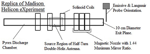
Figure 1. Diagram of the MadHeX replica including probe orientation. Measurements are recorded at the thruster exit plane. Thruster components are shown to scale.
The MadHeX exit plane is located ~0.75 m radially away from the facility sidewall as shown in Figure 2 and ~4.1 m from the rear facility wall or 3.5 m away from the graphite beam dump. During operation, the MadHeX replica is fed high-purity (99.9995%) argon propellant through stainless-steel Swagelok tubes with a 3 cm long nylon hose connector at the upstream discharge chamber inlet. Propellant flow is regulated by an MKS 1179A mass flow controller with an uncertainty of ~4–7% [20].
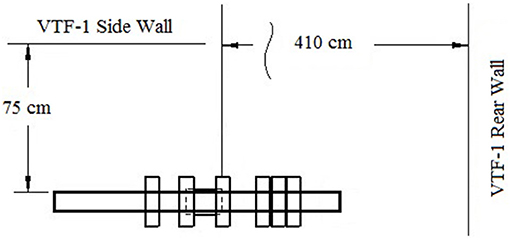
Figure 2. MadHeX replica orientation inside VTF-1 and distances between exit plane and facility walls.
A 13.56 MHz RF signal broadcasts from a solid-copper, half-turn double helix antenna measuring 13 cm in diameter and 18 cm long positioned between the second and third solenoid coils. A standing wave ratio of 1.05 or less is maintained during thruster operation for all measurements presented in this work with an uncertainty of ±0.05. A complete description of the RF network including cables and hardware, as well as measurement uncertainties and line losses, can be found in [10].
Vacuum Test Facility-1
The MadHeX replica is characterized inside Vacuum Test Facility 1 (VTF-1) at the Georgia Institute of Technology. VTF-1 measures 7 m long and 4 m in diameter. The pressure inside VTF-1 is measured using an externally-mounted Agilent BA 571 hot filament ionization gauge controlled by an Agilent XGS-600-gauge controller with a pressure measurement uncertainty of +20 to −10% [21]. Operating pressures presented are corrected for argon gas. Cycling among diagnostics is accomplished using a two-axis Parker Daedal 406XR precision linear motion stage system with an uncertainty of ±159 μm per motion stage.
To reach either the “High-Pressure” condition or the “Low-Pressure” condition, the facility is first evacuated to moderate vacuum (0.03 torr) by two 3800 cubic feet per minute (CFM) blowers and two 495 CFM rotary-vane pumps. To reach the “High-Pressure” condition (3 × 10⁻⁴ torr corrected for argon) from the 0.03 torr pressure environment, the blowers and rotary-vane pumps are shut down, and an Edwards STPXA3203 turbomolecular pump with a pumping speed of 3,200 l/s on nitrogen is operated. An Edwards GV80 dry scroll pump with a maximum pumping speed of 64.6 CFM serves as the backing pump for the turbomolecular pump.
To reach the “Low-Pressure” condition (1.2 × 10⁻⁵ torr corrected for argon) from the 0.03 torr pressure environment, six NRC/CVC Varian HS48-95000 fractionating diffusion pumps with copper baffles chilled by three Polycold fast-cycle water vapor cryopumps running on HC 1100 refrigerant are operated in addition to the aforementioned roughing pumps. The total diffusion pump configuration has an effective pumping speed of 125,000 l/s on argon gas [22].
Radio-Frequency-Compensated Emissive Probe
Plasma potential is measured using an 84 cm long, emitting, RF-compensated emissive probe with a thoriated-tungsten wire probe tip curved into a 0.127 mm diameter loop. Details on probe features and the RF compensation circuit can be found in [10]. Probe orientation is perpendicular to both the bulk plasma flow and magnetic field as recommended in [23]. The plane of the tungsten probe tip loop is oriented parallel to the thruster exit plane to allow gas flow through the loop as plasma exits the thruster [23]. The hardware used to bias the emissive probe and collect the I-V curves are detailed in [10].
Plasma potential is determined from the collected I–V curves using the inflection point method as described in Caruso [17], Sheehan and Hershkowitz [24], and Demidov et al. [25]. The uncertainty associated with using the inflection point method to determine plasma is on the order of ±Te/10. Emissive probe tip heating raised the resulting plasma potential measurement due to the voltage drop across the probe circuit by 1 V. Error inherent and restricted to power supply operation and data acquisition instrumentation introduces an additional 0.03% uncertainty into recorded values [26, 27]. Error due to local regression (LOESS) smoothing performed in the raw I–V curves falls within the error of the inflection point method and is considered negligible.
Retarding Potential Analyzer
The ion velocity distribution function (IVDF) is measured using a four-grid, RPA described in Xu [28]. The order of the grids from plasma to collector is: floating, electron repulsion, ion repulsion, electron suppression, and a collector. The collector is solid copper 0.8 mm thick and 3.15 cm in diameter [22]. The four RPA grids in front of the collector are composed of 316 stainless steel, 203 μm thick, and 3.15 cm in diameter with a physical grid transparency of 31% each. The grid pattern for each grid is aligned with the adjacent grids in an effort to achieve 31% open grid area for the entire RPA. The floating grid faces the open end of the helicon ion thruster for all RPA measurements. The chassis of the RPA remains electrically floating during operation in addition to the front grid. Hardware used to operate the RPA and collect the I–V curves analyzed are detailed in [10]. Prior to data collection, the RPA bias scheme is optimized by adjusting the potential of the electron repulsion and suppression grids separately to maximize collected current.
Uncorrected most-probable voltage is the ion repulsion grid bias voltage corresponding to the maximum derivative of the I–V curve recorded on the collector. This value corresponds to the relative velocity of the ion population in the exhaust plume. This value can be altered by subtracting the plasma potential measured with the emissive probe to yield the corrected most-probable voltage, an absolute velocity value more easily compared for performance between different thrusters. Due to the difference in calculated error between the plasma potential measured by the emissive probe and the method of determining the most probable voltage from the IVDF, both corrected and uncorrected most probable voltages are presented in this study. The error associated with estimating the most-probable voltage (uncorrected for plasma potential) for this analysis method is ~±4% [22]. Error inherent and restricted to power supply operation and data acquisition instrumentation introduces an additional 0.03% uncertainty into recorded values [26, 27]. Error due to LOESS smoothing of the raw I–V curves falls within the error of the analysis method for the RPA and is considered negligible.
Radio-Frequency-Compensated Langmuir Probe
Electron temperature and ion number density are calculated from the I–V curve acquired by an RF-compensated Langmuir probe placed at the exit plane. The Langmuir probe uses the 84 cm long body of the emissive probe but replaces the probe tip with a circular, planar tungsten probe tip 7.62 mm in diameter (dLP). The RF compensation circuit has been previously described in Caruso and Walker [10]. The axis of the probe is oriented perpendicular to the bulk propellant flow and magnetic field with the plane of the probe tip disc parallel to the exit plane as instructed in [25]. Power supplies and DAQ hardware, as well as associated uncertainties, for the RF-compensated Langmuir probe are described in Caruso and Walker [10].
An exponential fit is applied to the electron retardation region of the electron current curve to determine electron temperature Te (eV). The number of points available near the floating potential are increased by subtracting the ion contribution to the total probe current. Ion current is assumed proportional to the square root of the probe voltage and estimated using a linear fit as described in Chen [29]. Ion current is subtracted from the total probe current collected to generate curves of electron current (Ie) as a function of probe voltage [30]. Electron temperature is determined using Equation (1) for the derived Ie exponential fit equation vs. the probe bias voltage VPB as described in Jameson [31]. In order to prevent overestimation of the electron temperature in the absence of a compensation electrode at the probe tip, the exponential fit is applied to the segment of the electron retardation region closest to the floating potential and limited to only the most negative linear region in the log scale of the electron current–voltage trace [30]. The ion number density of the argon plasma is calculated using Equation (2) for a given probe tip diameter in meters, electron temperature in eV, and ion saturation current (Iis) in amps [32]:
Use of Equation (2) assumes ion number density and electron temperature to be bulk values with a 0.6 correction factor to account for reduced density of ions in the presheath as well as changes in electron temperature [32, 33]. In low-density plasmas, the collection area may exceed the probe area by several factors in size [34, 35]. To account for an increase in the effective collection area, the lower bound of uncertainty in ion number density has been increased 25% to account for an increase in collection area of up to four times the planar probe tip area. Ion saturation current is calculated as the average current for all current values from 5 to 50 V below the floating potential [36]. The uncertainty in the calculated electron temperatures using this method is up to ±0.8 eV maximum for the “Low-Pressure” condition and up to ±0.2 eV for the “High-Pressure” condition; the standard uncertainty in the calculated ion number density is ±50% [36] with an extension of the lower uncertainty bound to −75%. Error inherent and restricted to power supply operation and data acquisition instrumentation introduces an additional 0.03% uncertainty into recorded values [26, 27].
Results
The IVDF for the nominal or “High-Pressure” condition (High P) at 2 cm3/min volumetric flow rate, shown in Figure 3A, has a most probable voltage (Vmp) of 18.3 V (±4.03%) corrected (Vmp,corr) to 14.1 V (±4.03% and ±1 V) at the thruster exit plane as shown in Figure 4. IVDFs recorded during operation at the “Low-Pressure” condition (Low P) for volumetric flow rates from 1.3 to 60 cm3/min shown in Figure 3B through Figure 3D shift to lower most probable voltages (Vmp) with increasing supplied argon flow rate. Most probable voltages range from a maximum of 108 V at 1.3 cm3/min to a minimum of 27 V at 60 cm3/min supplied argon volumetric flow rate. Corrected most probable voltages (Vmp,corr) range from a maximum of 52.3 V at 4 cm3/min to a minimum of 12.8 V at the 30 cm3/min operating condition. Plasma potentials for flow rates at 40 cm3/min and above are assumed to be equal to ~0 V due to negative recorded plasma potential values from the emissive probe caused by negative-sheath effects during emission [37]. Plasma potentials are plotted in Figure 4 for both pressure conditions with results from the “High-Pressure” condition represented by horizontal, gray lines.
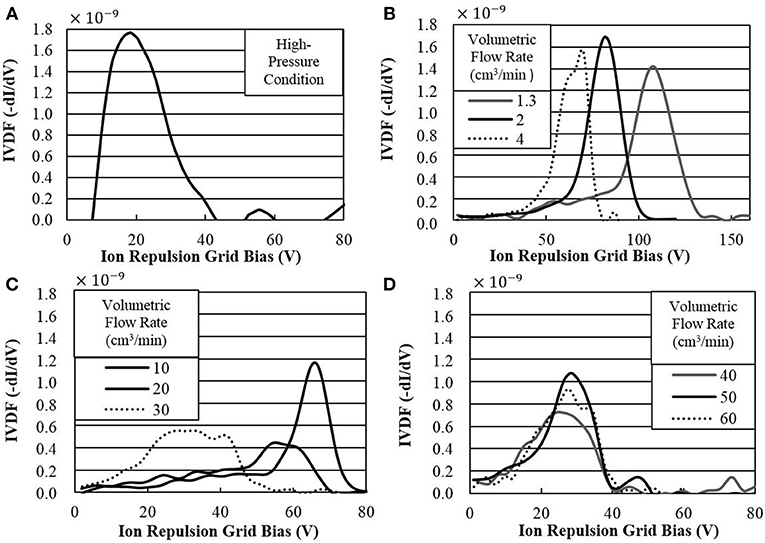
Figure 3. IVDFs (uncorrected) measured at the exit plane for (A) “High-Pressure” condition and (B–D) “Low-Pressure” condition.
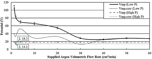
Figure 4. Most probable voltages, corrected (Vmp, corr) and uncorrected (Vmp) at the “Low-Pressure” (Low P) and the “High-Pressure” (High P) conditions.
Figures 5, 6 compare the electron temperatures and ion number densities, respectively between both pressure conditions. Electron temperature measured during thruster operation at the “Low-Pressure” condition [Te (Low P)] shown in Figure 5 decreases from 7.3 eV (±0.8 eV) at the 2 cm3/min argon volumetric flow rate to 1.0 eV (±0.3 eV) at the 60 cm3/min argon volumetric flow rate. Electron temperature at the “High-Pressure” condition [Te (High P)] is 1.7 eV (±0.2 eV) represented by the thick gray line in Figure 5. Ion number density at the “Low-Pressure” condition [ni (Low P)] is a maximum at the 10 cm3/min operating condition with a value of 3.5 × 10¹⁴ ions/m3 as shown in Figure 6. Above 10 cm3/min, ion number density asymptotically approaches a final value of ~1.4 × 10¹⁴ ions/m3 at 60 cm3/min. Ion number density at the “High-Pressure” condition [ni (High P)] is 1.4 × 10¹⁴ ions/m3 (+50%/−75%) represented by the thin gray line in Figure 6.
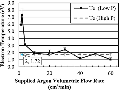
Figure 5. Electron temperatures recorded at the “Low-Pressure” (Low P) and 2 cm3/min flow rate “High-Pressure” (High P) conditions.
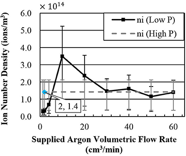
Figure 6. Ion number densities recorded at the “Low-Pressure” (Low P) and 2 cm3/min flow rate “High-Pressure” (High P) conditions.
Discussion
Exit plane plasma properties are compared between operation at the “Low-Pressure” condition for supplied argon volumetric flow rates of 1.3–60 cm3/min and at the “High-Pressure” condition at 2 cm3/min supplied argon volumetric flow rate. When considering all available data recorded, no individual supplied flow rate at the “Low-Pressure” condition reproduces all the plasma property values recorded at the nominal flow rate at the “High-Pressure” condition. The inability of plasma properties to be reproduced at a single adjusted flow rate at the “Low-Pressure” condition is a result of the differing magnitudes of influence neutral ingestion effects have on individual plume properties. Changes in plasma plume properties due to changes in neutral ingestion and supplied propellant are evaluated using collision theory. This method is considered valid as the physics of interest occur in the downstream region (60 cm from the downstream edge of the antenna) and should not be subject to axial variations due to local ionization physics in the source region [18]. The effects of increased propellant flow rate due to neutral ingestion and the influence these atoms have on the properties of interest are discussed in depth in the following sections.
Ion Beam Velocity and Collision Frequency
In a previous study of neutral ingestion effects on ion beam behavior [10], the accelerated ion population at the “Low-Pressure” condition was observed to gain kinetic energy as ions were accelerated along the potential drop in the downstream direction of the main thruster axis. This behavior corresponds with the trend of increasing most probable voltages with increasing downstream distance from the thruster exit plane. For the “High-Pressure” condition, ion energy was observed to decrease with increasing downstream distance from the exit plane due to energy losses correlating with increased collisions between the accelerated ion population and other plume species. Results from [10] have informed the decision in this study of the types of collisions to consider. The primary collision types evaluated in this study include charge-exchange collisions between beam ions and ingested neutral argon atoms, momentum-exchange collisions between beam ions and ingested neutral argon atoms, and ionization collisions between electrons and ingested neutral argon atoms. Ionizing collisions will be considered in Section Ion Production.
Charge-exchange collisions occur when a fast ion from the accelerated ion beam collides with a neutral atom resulting in the formation of a slow ion and fast neutral atom. This reaction described in Equation (3), occurs both close to and downstream of the exit plane resulting in a reduction of ion energy [38] as observed during operation at higher neutral ingestion flow rates [10]. Momentum-exchange collisions also result in a reduction of beam ion energy due to collisions with other plume species. Momentum-exchange collisions between beam ions and ingested neutral atoms are of particular interest as they result in a net decrease in overall ion beam energy.
In order to quantify the magnitude of the effect of parasitic collisions on ion beam energy, the collision frequencies for both charge-exchange and momentum exchange collisions are calculated using Equation (4). Collision frequency (ν) is a function of the ion beam velocity () calculated using Equation (5) and the corresponding mean free path (λ) calculated using Equation (6). Ion beam velocity is a function of the corrected most probable voltage [difference in most probable voltage (Vmp) and plasma potential (Vp)] and argon mass in kg.
Mean free paths for each collision type are a function of the neutral argon number density (nn) calculated using Equation (7) and the collisional cross-section (σ). In this work, σ = 7 × 10⁻¹⁹ m2 for ion energies up to 100 eV for charge transfer collisions and σ = 1 × 10⁻¹⁸ m2 for momentum exchange collisions [39]. Neutral number density is representative of the ingested neutral argon population for each pressure condition and corresponds to the ingested volumetric flow rates determined using Equation (8).
The neutral ingestion volumetric flow rates for both pressure conditions and the corresponding neutral number densities are displayed in Table 1. The neutral ingestion volumetric flow rate (Qingested) increases with the partial pressure of argon (Pargon) in Torr, the area of the thruster (A), and the conductance of the thruster area (ηc). For the MadHeX replica, the exit plane area is 0.0079 m2 and the conductance is assumed to be 1. Ingested neutral temperature (Tn) is assumed to be 298 K representing the maximum possible ingested neutral argon flow rate. The mass of the argon propellant (Ma) is 39.948 AMU.
For each increasing argon volumetric flow rate, the operating chamber pressure was expected to increase. While an overall increase in pressure of 3.0 × 10⁻⁶ torr was observed across the full supplied propellant volumetric flow rate of 1.3–60 cm3/min, the pressure increase remained below the overall test campaign pressure fluctuations and was well within the overall 30% error associated with pressure measurements with the Agilent BA 571 hot filament ionization gauge discussed in Section II.B. For this reason, mean free paths related to the ingested argon neutrals for each collision type shown in Table 2, are considered to change negligibly across the full range of testing conditions at the “Low-Pressure” condition.

Table 1. Neutral argon number density and volumetric flow rate values for the “Low-Pressure” condition and the “High-Pressure” condition.

Table 2. Mean free path lengths for charge-exchange (λCE) and momentum-exchange (λME) collisions for the “Low-Pressure” and “High-Pressure” conditions.
Ion beam velocities shown in Figure 7 at the “Low-Pressure” condition range from ~2.8 to 7.6 km/s greater than the 8.3 km/s beam velocity at the “High-Pressure” condition due to the higher ion energies discussed previously with the exception of the 30 cm3/min case. While plasma potential at the 30 cm3/min case is 15.5 V > 0 V, it is the last observed case before plasma potentials become negative due to negative-sheath effects during probe tip emission as previously discussed in Section Results. If the 30 cm3/min case is also presumed to experience negative-sheath effects and a value of 0 V is substituted into Equation (5) for Vp, ion beam velocity is increased to a final value of 11.7 km/s which is more consistent with the observed beam velocity trend at the “Low-Pressure” condition.
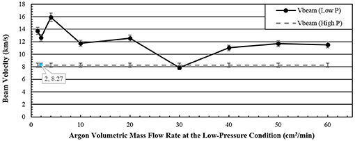
Figure 7. Ion beam velocities at the “Low-Pressure” (Low P) and 2 cm3/min flow rate “High-Pressure” (High P) conditions.
Despite the consistently higher beam velocities at the “Low-Pressure” condition shown in Figure 7 when substituting the 11.7 km/s beam velocity for the 30 cm3/min case discussed earlier, both the charge-exchange collision frequency (CEX) and momentum-exchange collision frequency (MEX) at the “High-Pressure” condition (High P) for the 2 cm3/min case shown in Figure 8 far exceed all collision frequencies across the full range of supplied argon volumetric flow rates at the “Low-Pressure” condition (Low P). Both charge-exchange and momentum-exchange collisions at the “High-Pressure” condition occur between 2.5 and 5 times more often than corresponding collision types at the “Low-Pressure” condition. From Equation (4), we can conclude that the significantly lower mean free paths for both collision types at the “High-Pressure” condition, resulting from the order of magnitude difference in ingested neutral argon atom number density between the two pressure conditions, govern the resulting higher collision frequencies at the “High-Pressure” condition. Error associated with calculated collision frequencies includes the ion gauge pressure measurement uncertainty and RPA error.
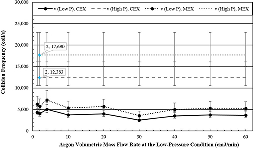
Figure 8. Charge-exchange (CEX) and momentum-exchange (MEX) collision frequencies at the “Low-Pressure” (Low P) and 2 cm3/min flow rate “High-Pressure” (High P) conditions.
Parasitic collisions such as charge-exchange and momentum-exchange collisions between beam ions and ingested neutral atoms reduce the overall energy in the accelerated ion beam. While increased supplied argon volumetric flow rate results in a decrease in beam velocity with increasing flow rate at the “Low-Pressure” condition, the effect of ingested neutral argon atom number density is minimal due to sufficient chamber pumping speed maintaining the mean free paths cited in Table 2 which are far longer than the length scales of the thruster. This results in a relatively constant neutral ingestion number density that yields relatively constant mean free paths for beam ions between charge-exchange and momentum-exchange collisions. Despite the decreasing beam velocity observed at higher volumetric flow rates at the “Low-Pressure” condition, excluding the 30 cm3/min case, beam velocity never drops to the 8.3 km/s observed at the “High-Pressure” condition. While there is less, supplied argon propellant at the “High-Pressure” condition the frequency of charge-exchange and momentum-exchange collisions are much greater, reducing the energy of the ion beam due to the significantly shorter mean free paths corresponding to higher ingested neutral number density. Increasing the supplied propellant flow rate at lower environmental pressures does not proportionally result in the same ion beam energy losses as observed during operation at higher environmental pressures due to the influence of ingested neutral number density on collision frequency near the thruster exit plane.
Ionization Balance and Electron Cooling
In the previous section, ion beam velocity is observed to decrease as supplied propellant flow rate is increased at the “Low-Pressure” condition. Since collision frequency between beam ions and ingested neutral argon atoms remains relatively constant within the margins of error across the full range of supplied argon flow rate considered, as shown in Figure 8, an examination of the ionization balance is required. A decrease in ion energy with increasing propellant flow rate is expected as more argon atoms are available for ionization and as the plasma becomes more collisional in the source region due to the increase in propellant number density. Examination of the ionization balance described in Equation (9) should indicate if additional loss mechanisms are present.
A constant ratio of maximum ion energy (Eion, Max) in volts to electron temperature (Te) in eV will indicate that changes in ionization balance are responsible for decreasing ion energies and decreasing electron temperatures. Calculated energy ratios are presented in Figure 9 for both pressure conditions. Uncertainty, shown is a composite of associated error with measurements of the most probable voltage and variations in recorded electron temperature. Larger uncertainties occur for the 20 cm3/min and 60 cm3/min cases due to the fluctuations of electron temperature on the order of 0.5 eV or 50% of the recorded electron temperatures. The ratio presented in Equation (9) is directly proportional to electron temperature propagating the uncertainties in electron temperature values discussed in Section Results into the ionization balance.
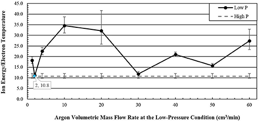
Figure 9. Ion energy ratios for the “Low-Pressure” (Low P) and 2 cm3/min flow rate “High-Pressure” (High P) conditions.
The ratio of ion energy to electron temperature varies from 11.2 to 34.6 across the full range of supplied argon volumetric flow rates considered at the “Low-Pressure” condition. The 2 cm3/min and the 30 cm3/min flow rates at the “Low-Pressure” condition show a ratio between ion energy and electron temperature approximately equal to the 10.8 ratio observed at the “High-Pressure” condition implying that changes in ionization balance lead to the decreases in recorded electron temperature shown in Figure 5 [40].
For the remaining cases at the “Low-Pressure” condition, the electron temperatures are lower than expected for the corresponding ion energy implying that additional losses in energy in the plasma plume remain unaccounted. Similar to the energy losses that occur for the accelerated ion population, electrons exhibit a cooling behavior during travel through high neutral density environments due to repeated collisions with neutral atoms [41]. Electron cooling behavior has been experimentally shown to scale with neutral density and results in a reduction in electron temperatures [41]. Energy transferred from hot plume electrons to other plume species results in a decrease in electron temperature observed as supplied argon propellant flow rate is increased.
Increasing the supplied propellant volumetric flow rate in an effort to reproduce plasma properties altered via an increase in ingested neutral argon atoms at higher environmental pressures fails to reproduce plasma properties of equal energy or electron temperature. While the differences in ion energy and electron temperature at the 2 cm3/min case at the “Low-Pressure” condition are due to changes in the ionization balance, increasing supplied argon flow rates introduces electron cooling behavior between the additional argon atoms and hot plume electrons. This results in a decrease in electron temperature disproportionate to the changes in ion energy.
Ion Production
The final plasma plume property of interest, ion number density at the exit plane, remains to be examined. Due to the high levels of uncertainty associated with ion number density measurements, no clear conclusions regarding plume ionization of ingested neutral argon atoms can be gleaned from examination of Figure 6. Previous literature studies regarding the effect of neutral ingestion on helicon ion thrusters posit that ion number density may be enhanced with the recirculation of neutral propellant inside the discharge chamber [1]. Ions formed from ingested propellant in the area of influence of the potential drop may be accelerated and contribute to thrust generation enhancing performance measurements when operated at higher environmental pressures. Ion production rates at the thruster exit plane are calculated using Equation (10) where electron number density (ne) is assumed equal to the ion number density (ni) recorded earlier, neutral number density (nn) comes from Table 1, and the argon ionization rate constant (Kiz) is determined via interpolation from 3.16 in [42] for the corresponding electron temperature. Values are presented in Table 3 for both pressure conditions. Ion production rates are incalculable for electron temperatures below 1.5 eV.
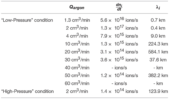
Table 3. Ion production rates and mean free paths for the “Low-Pressure” and the “High-Pressure” conditions.
Corresponding mean free paths for each case are calculated using Equation (6) where the ionization cross section is determined using Equation (11) using the corresponding argon ionization rate constant and dividing by the electron beam velocity (ve−) calculated using Equation (12). In Equation (12), electron mass (me) is given in kilograms.
Ion production rates at the “Low-Pressure” condition for all cases below 40 cm3/min argon propellant flow rate, exceed the rate of ionization of ingested argon propellant at the “High-Pressure” condition. However, consideration of the mean free path lengths of ionization, 0.4 km at minimum, implies that ionization of ingested argon neutrals is negligible at the thruster exit plane.
While ionization of ingested argon neutral atoms is unlikely to occur at the exit plane, the large mean free path lengths of the momentum exchange and charge exchange collisions discussed in Section Ion Beam Velocity and Collision Frequency implies that additional argon neutral interactions may occur inside the thruster discharge chamber where electron temperatures are higher. Electron temperature and ion number density measurements extending upstream from the exit plane to the source region are required to determine the likelihood of ingested neutral argon atom ionization inside the thruster discharge chamber. It is unclear from the results of this study the full impact of ingested propellant ionization on thruster operation.
Conclusion
Increasing the supplied propellant volumetric flow rate to an RF discharge operating in a low background pressure environment in an effort to reproduce plasma properties affected by neutral ingestion at higher environmental pressures fails to reproduce ion beams of equal energy or density and in many cases may not be desirable. The 2 standard cm3/min volumetric flow rate at the “High-Pressure” condition has lower ion energy and electron temperature than the corresponding flowrate condition at the “Low-Pressure” condition. The only plasma property to benefit from neutral ingestion at the “High-Pressure” condition is ion number density which may (depending on the magnitude of the difference between both operating pressure conditions) result in improved performance at higher background pressure. The absolute magnitude of this effect will be dependent upon nominal thruster operating conditions and facility background pressures.
For the “High-Pressure” condition, charge and momentum exchange collisions result in reduced ion beam energies unfavorable to increased thruster performance. In general, increases in volumetric flow rate at the “Low-Pressure” condition required to match properties recorded at the “High-Pressure” condition exceeded the total predicted thruster flow rate (supplied and ingested flow rates summed together). Plasma plume properties recorded at high facility background pressures are not reproducible at lower facility background pressures even when the thruster flow rate is increased to account for the artificial pressure increase in the thruster discharge chamber due to neutral ingestion at the higher background pressure. RF ion thruster thrust calculations performed using plasma plume properties recorded at high facility background pressures are not predictive of thrust values calculated for the same thruster operating at orders of magnitude lower facility pressures, even when propellant flow rates are adjusted to compensate for neutral ingestion. Further studies are required to determine the highest allowable facility background pressure suitable for performance evaluation of RF ion thrusters that will enable accurate performance prediction of the thruster under study when operated in a more space-like environment.
Author Contributions
Experimental set up, data collection, and analysis were performed by NC. Review of findings and analysis were performed by MW.
Funding
This experimental research is supported by the Air Force Office of Scientific Research through Grant No. FA9550-10-1-0396.
Conflict of Interest Statement
The authors declare that the research was conducted in the absence of any commercial or financial relationships that could be construed as a potential conflict of interest.
Acknowledgments
The authors would like to thank Samuel Langendorf, Aaron Schinder, and Jonathan Walker for their help with the diagnostics and data collection. The authors also extend their gratitude to Jason Frieman who was heavily involved in the preliminary experiments of the MadHeX replica.
References
1. Charles C. Plasmas for spacecraft propulsion. J Phys D Appl Phys. (2009) 42:163001. doi: 10.1088/0022-3727/42/16/163001
2. Pottinger S, Lappas V, Charles C, Boswell R. Performance characterization of a helicon double layer thruster using direct thrust measurements. J Phys D Appl Phys. (2011) 44:235201. doi: 10.1088/0022-3727/44/23/235201
3. Aanesland A, Rafalskyi D, Bredin J, Grondein P, Oudini N, Chabert P. et al The PEGASES gridded ion-ion thruster performance and predictions. IEEE Transac Plasma Sci. (2015) 43:321–6. doi: 10.1109/TPS.2014.2369534
4. Gilland J. Helicon wave physics impacts on electrodeless thruster design. Proceedings of the 28th International Electric Propulsion Conference. Toulouse: Electric Rocket Propulsion Society, IEPC Paper 0150-0303 (2003).
5. Plihon N, Chabert P, Raimbault JL. Helicon Double Layer Thruster Concept for High Power NEP Missions: Final Report. ESA ID: 04/3101 (2006).
6. Siddiqui M, Cretel C, Synowiec J, Hsu A, Young J, Spektor R. First performance measurements of the phase four RF thruster. Proceedings of the 35th International Electric Propulsion Conference, Electric Rocket Propulsion Society, IEPC Paper 2017-431. Atlanta, GA (2017).
7. Cassady L, Longmier B, Olsen C, Ballenger M, McCaskill G, Ilin A, et al. VASIMR performance results. Proceedings of the 46th AIAA/ASME/SAE/ASEE Joint Propulsion Conference & Exhibit, AIAA 2010-6772. Nashville, TN (2010).
8. Takahashi K, Charles C, Boswell R, Ando A. Effect of magnetic and physical nozzles on plasma thruster performance. Plasma Sources Sci Technol. (2014) 23:044004. doi: 10.1088/0963-0252/23/4/044004
9. Fruchtman A. The thrust of a collisional-plasma source. IEEE Transac Plasma Sci. (2011) 39:530–9. doi: 10.1109/TPS.2010.2089067
10. Caruso NRS, Walker MLR. Neutral ingestion effects on plume properties of a radio-frequency plasma discharge. J Propulsion Power (2018) 34:58–65. doi: 10.2514/1.B36404
11. Hofer RR, Peterson PY, Gallimore AD. Characterizing vacuum facility backpressure effects on the performance of a hall thruster. Proceedings of the 27th International Electric Propulsion Conference, Electric Rocket Propulsion Society, IEPC Paper 2001-045. Pasadena, CA, (2001).
12. Gilland J, Breun R, Hershkowitz N. Neutral pumping in a helicon discharge. Plasma Sources Sci Technol. (1998) 7:416–22. doi: 10.1088/0963-0252/7/3/020
13. Schloeder N, Frieman J, Walker M. Facility effects on helicon plasma source operation. Proceedings of the 50th AIAA/ASME/SAE/ASEE Joint Propulsion Conference, AIAA Propulsion and Energy Forum, AIAA 2014-3713. Cleveland, OH (2014). doi: 10.2514/6.2014-3713
14. Wiebold M. The Effect of Radio-Frequency Self Bias on Ion Acceleration in Expanding Argon Plasmas in Helicon Sources. Ph.D. Dissertation, Electrical and Computer Engineering Dept., Univ. of Wisconsin–Madison, Madison, WI (2011).
15. Wiebold M, Scharer JE. Experimental observation of ion beams in the madison helicon experiment. Phys Plasmas (2011) 18:063501. doi: 10.1063/1.3596537
16. Wiebold M, Sung Y, Scharer JE. Ion acceleration in a helicon source due to the self-bias effect. Phys Plasmas (2012) 19:053503. doi: 10.1063/1.4714605
17. Caruso N. Facility Effects on Helicon Thruster Operation. Ph.D. Dissertation, Aerospace Engineering Dept., Georgia Inst. Of Technology, Atlanta, GA (2016).
18. Chen FF, Sudit ID, Light M. Downstream physics of the helicon discharge. Plasma Sources Sci Technol. (1996) 5:173–80. doi: 10.1088/0963-0252/5/2/009
19. Franck CM, Grulke O, Klinger T. Mode transitions in helicon discharges. Phys Plasmas (2003) 10:323–5. doi: 10.1063/1.1528903
20. Snyder JS, Baldwin J, Frieman J, Walker M, Hicks N, Polzin K, et al. Flow Control and Measurement in Electric Propulsion Systems: Towards an AIAA Reference Standard, Proceedings of the 33rd International Electric Propulsion Conference, Electric Rocket Propulsion Soc. (ERPS), IEPC Paper 2013-425, Washington DC, 2013.
21. Tilford CR. Sensitivity of hot cathode ionization gages. J Vacuum Sci Technol A (1985) 3:546–50. doi: 10.1116/1.572991
22. Williams L. Ion Acceleration Mechanisms of Helicon Thrusters. Ph.D. Dissertation, Aerospace Engineering Dept., Georgia Inst. Of Technology, Atlanta, GA (2013).
23. Lafleur T, Charles C, Boswell RW. Detailed plasma potential measurements in a radio frequency expanding plasma obtained from various electrostatic probes. Phys Plasmas (2009) 16:044510. doi: 10.1063/1.3125314
24. Sheehan JP, Hershkowitz N. TOPICAL REVIEW: emissive Probes. Plasma Sources Sci Technol. (2011) 20:063001. doi: 10.1088/0963-0252/20/6/063001
25. Demidov VI, Ratynskaia SV, Rypdal K. Electric probes for plasmas: the link between theory and instrument. Rev Sci Instruments (2002) 73:3409–39. doi: 10.1063/1.1505099
26. “User Manual for Keithley Sourcemeter ” Series 2400 Data Sheet Keithley Instruments p. 5. Available online at: www.Keithley.com
27. Keithley Instruments. Keithley Model 6485 Picoammeter Instruction Manual, 6485-901-01 Rev. A. Cleveland, OH (2001). p. A-2.
28. Xu KG. Ion Collimation and In-Channel Potential Shaping Using In- Channel Electrodes for Hall-Effect Thruster. Ph.D. Dissertation, Aerospace Engineering Dept., Georgia Inst. of Technology, Atlanta, GA (2012).
29. Chen F. Saturation ion currents to langmuir probes. J Appl Phys. (1965) 36:675–78. doi: 10.1063/1.1714200
30. Sudit D, Chen F. RF compensated probes for high-density discharges. Plasma Sources Sci Technol. (1994) 3:162–8. doi: 10.1088/0963-0252/3/2/006
31. Jameson K. Investigation of Hollow Cathode Effects on Total Thruster Efficiency in a 6 kW Hall Thruster. Ph.D. Dissertation, Aerospace Engineering Dept., Univ. of California, Los Angeles, CA (2008).
32. Merlino R. Understanding langmuir probe current-voltage characteristics. Am J Phys. (2007) 75:1078–85. doi: 10.1119/1.2772282
33. Steinbruchel C. A new method for analyzing langmuir probe data and the determination of ion densities and etch yields in an etching plasma. Vac Sci Technol A Vacuum Surf Films (1990) 8:1663–67.
34. Sheridan TE. How big is a small langmuir probe? Phys Plasmas (2000) 7:3084. doi: 10.1063/1.874162
35. Lee D, Hershkowitz N. Ion collection by planar langmuir probes: sheridan's model and its verification. Phys Plasmas (2007) 14:033507. doi: 10.1063/1.2715557
36. Reid BM. The Influence of Neutral Flow Rate in the Operation of Hall Thrusters. Ph.D. Dissertation, Aerospace Engineering Dept., Univ. of Michigan, Ann Arbor, MI (2009).
37. Campanell MD. Negative plasma potential relative to electron-emitting surfaces. Phys Rev E. (2013) 88:033103. doi: 10.1103/PhysRevE.88.033103
38. Crofton M, Boyd I. Momentum modeling of a hall thruster plume. Proceedings of the 33rd International Electric Propulsion Conference, Electric Rocket Propulsion Soc. (ERPS), IEPC Paper 2013-374, Washington DC, 2013.
39. Phelps AV. Cross sections and swarm coefficients for nitrogen ions and neutrals in N2 and argon ions and neutrals in ar for energies from 0.1 eV to 10 keV. J Phys Chem Reference Data (1991) 20:557. doi: 10.1063/1.555889
40. Lafleur T, Cannat F, Jarrige J, Elias P, Packan D. Electron dynamics and ion acceleration in expanding-plasma thrusters. Plasma Sources Sci Technol. (2015) 24:065013. doi: 10.1088/0963-0252/24/6/065013
41. Fossum E, King L. Effects of neutral density on electron temperature and mobility in a crossed-field trap. Proceedings of the 44th AIAA/ASME/SAE/ASEE Joint Propulsion Conference & Exhibit, Joint Propulsion Conferences. Hartford, CT (2008).
Keywords: neutral ingestion, facility effects, RF discharge, ion density, electron temperature
Citation: Caruso NRS and Walker MLR (2019) Effects of Ingested vs. Injected Propellant on Radio-Frequency Discharge Plasma Properties. Front. Phys. 6:161. doi: 10.3389/fphy.2018.00161
Received: 10 August 2018; Accepted: 28 December 2018;
Published: 17 January 2019.
Edited by:
Francesco Taccogna, Italian National Research Council, ItalyReviewed by:
Jayr Amorim, Instituto Tecnológico de Aeronáutica, BrazilFabrizio Paganucci, Università degli Studi di Pisa, Italy
Copyright © 2019 Caruso and Walker. This is an open-access article distributed under the terms of the Creative Commons Attribution License (CC BY). The use, distribution or reproduction in other forums is permitted, provided the original author(s) and the copyright owner(s) are credited and that the original publication in this journal is cited, in accordance with accepted academic practice. No use, distribution or reproduction is permitted which does not comply with these terms.
*Correspondence: Natalie R. S. Caruso, bmNhcnVzb0BzcGFjZS5ucmwubmF2eS5taWw=
 Natalie R. S. Caruso
 Mitchell L. R. Walker