
94% of researchers rate our articles as excellent or good
Learn more about the work of our research integrity team to safeguard the quality of each article we publish.
Find out more
ORIGINAL RESEARCH article
Front. Mech. Eng. , 26 June 2020
Sec. Micro- and Nanoelectromechanical Systems
Volume 6 - 2020 | https://doi.org/10.3389/fmech.2020.00035
This article is part of the Research Topic Nanofilms and Nanostructures for Energy Applications View all 6 articles
Nanoporous nickel–copper metallic foams were electrodeposited using the Dynamic Hydrogen Bubble Template (DHBT) technique. The effect of deposition parameters (applied current density and deposition time) on surface morphology of the obtained layers was studied with the aid of SEM. The Ni–Cu electrodeposited layers were characterized by a porous dendritic structure. According to EDX analysis, increasing both the deposition time and applied current density leads to an increase in the Ni content in the nano-foams. These foams were tested as electrodes for supercapacitors in 1 M KOH solutions. From potentiodynamic polarization test, the corrosion rate was accelerated when increasing the deposition time up to 150 s as well as the deposition current density up to 1.8 A/cm2. The electrochemical behavior of the material was studied by cyclic voltammetry aiming at its application as positive electrodes for supercapacitors, using 1 M KOH solution. From cyclic voltammetry, the increase in applied current density and the deposition time leads to an increase in the current density and total charge measured by cyclic voltammetry, having a beneficial effect on the electrochemical activity of the Ni–Cu films. The highest forward current peak was obtained for nickel–copper foams deposited at 2 A/cm2 for 150 s. From the EIS test, the polarization resistance (Rp) decreased when increasing the current density as well as electrodeposition time. The lowest polarization resistance was recorded for porous Ni–Cu layers electrodeposited at 2 A/cm2 for 150 s, indicating high electrochemical activity of this layers (35.02% Cu) as electrodes for supercapacitors.
Supercapacitors, one of the energy storage systems, are able to store and deliver energy at relatively high rates. The mechanism of energy storage is the simple charge separation at the electrochemical interface between the electrode and the electrolyte (Zaharaddeen et al., 2016). The supercapacitors have higher energy density than that of conventional dielectric capacitors. The high cycle life and high power, made the supercapacitor fit a lot of applications like electric vehicles, cell phones, quick charge applications, e.g., wireless power tools, and medical applications (Conway, 1999). Based on the materials used in the synthesizing of supercapacitors, they are classified into two types, double layer supercapacitors and pseudo capacitors (redox supercapacitors) (An et al., 2001). There is an interest in using nano-structured materials for supercapacitor electrodes due to increased surface area and improved capacitive performance (Arbizzani et al., 2001). There are methods for synthesizing supercapacitor materials, such as chemical bath deposition, chemical vapor deposition (Brinker et al., 1991), sol–gel method (Burke, 2000), dealloying, and electrochemical deposition (Arico et al., 2005). The benefits of the electrodeposition method include mass production, low capital investment costs, and high control on parameters such as film thickness, uniformity, and deposition rate (Nikolić et al., 2006a; Abdel-Karim et al., 2019). The dynamic hydrogen bubbling template (DHBT) process is a simple, low-cost method for the synthesizing of porous metal foams (Shin and Liu, 2004; Mohamed et al., 2019). The electrodeposited NMFs are formed on stainless steel substrates of high electronic conductivity and are beneficial for production of supercapacitor electrodes since the active materials are directly applied on the current collector (Shin et al., 2013).
The surface morphology of the porous metal foam obtained by this process depends mainly on the electrodeposition parameters and bath composition. Porosity can also be adjusted by additives in the electrolyte that may cause bubble stabilization and hinder collision of bubbles and thus can affect the metal deposition itself (Nikolić et al., 2006b).
From previous papers, copper and nickel NMFs have been the most studied materials fabricated by electrodeposition using the dynamic hydrogen template method (Abdel-Karim et al., 2019). According to our knowledge, few papers have discussed the production of NMFs containing transition metals such as nickel and cobalt, as low-cost alternatives to noble metals for high catalytic reactivity applications (Tan et al., 2010; Nam et al., 2011; Santos et al., 2015a). In the present work, porous nickel–copper metallic foams were electrodeposited on stainless steel substrates using the dynamic hydrogen bubbling template technique. This work discusses the effect of working parameters, such as the applied current density as well as deposition time, on the surface morphology and properties of electrodeposited layers. The electrochemical behavior of these materials as electrodes for supercapacitors will be studied in alkaline solution.
The electrodeposition process was conducted on as-polished 304 stainless steel substrate with the chemical analysis shown in Table 1. The specimens were machined to be of dimensions 15 ×40 ×0.4 mm. All samples were subjected to the chemical activation pretreatment in a solution of 38% HCl (wt. percent). This was followed by rinsing with distilled water in order to remove any traces of chemicals.
The electrodeposition cell was composed of graphite anode and stainless steel cathode that were connected to the positive and negative poles of a dc power supply type Chroma 62000P-100-25 with a Chroma 62000P software. The two electrodes were immersed in an electrolyte containing Ni and Cu salts in addition to some additives. Table 2 shows bath chemical composition and all the working parameters such as temperature, deposition current density, and deposition time. The electrolyte used was composed of 0.5 M NiSO4.7H2O, 0.01 M CuSO4.5H2O, 1.5 M H2SO4, and 1 M HCl.
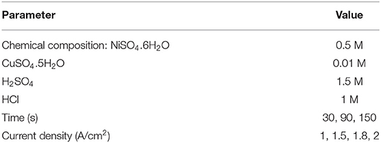
Table 2. Electrolytic bath composition and electrodeposition working conditions of Ni–Cu porous films.
Electrochemical measurements were carried out using electrochemical work station, Gamry PCI300/4 Potentiostat/Galvanostat/Zra analyzer, with a personal computer. A three-electrode cell composed of electrodeposited specimen was used as a working electrode with an active area of 0.87 cm2, a Pt counter electrode, and a Ag/AgCl reference electrode. Polarization tests were carried out at a scan rate of 2 mV/min at 25°C. The Echem Analyst 5.21 statistically fits the experimental data to the Stern–Geary model for a corroding system and automatically selects the data that lies within the Tafel's region to the corrosion potential from open circuit potential “OCP.” The Echem Analyst calculates the corrosion rate, corrosion current density, corrosion potential, anodic and cathodic Tafel's slopes.
Cyclic voltammetry measurements were carried out by sweeping linearly the potential from the starting potential into the positive direction (−0.2 to +0.8 V) at scan rate of 75 mV/s to form one complete cycle. All electrochemical measurements were carried out using 1 M KOH. All measurements for all testing techniques were taken as an average of three measurements.
Figure 1 shows the relation between weight change after electrodeposition as a function of applied current density A/cm2 as well as deposition time in seconds. The obtained results for rate of electrodeposition indicated that applied current plays a significant role in electrodeposition process. The time that is used is also a factor that improves the mass of deposited Ni–Cu foams. The electrodeposited time increased with increasing electrodeposition current density as well as deposition time. There was a remarkable reduction in the rate of electrodeposition, for samples electrodeposited at 1.8 A/cm2. This might be due to high porosity of the layer deposited at 1.8 A/cm2, which will be described in the following section.
Figures 2–5 illustrate the morphology of porous Ni–Cu nanostructures produced by electrodeposition using a high cathodic current in acidic electrolytes, where the existing pores result from hydrogen (H2) bubble evolution during the deposition process. The porous structure results from the so-called “Hydrogen Bubble Templating Mechanism” (Herraiz-Cardona et al., 2013; Santos et al., 2015b). Metal deposition occurs preferentially in the interstices between H2 bubbles, forming metal grains. Hydrogen is chosen not only because of its role as a “so-called” template but also due to its low cost, low toxicity, and, most importantly, needless of template removal, as typically required in other synthetic strategies. In fact, the hydrogen template-assisted electrodeposition is a one-step method because hydrogen is automatically detached from the growing porous layer during the deposition process (Cardoso et al., 2015).
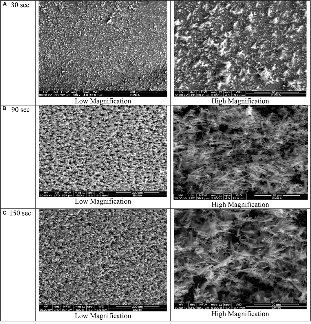
Figure 2. SEM images of porous Ni–Cu layers electrodeposited on AISI 304 stainless steel for (A) 30 s, (B) 90 s, (C)150 s. at current density 1 A/cm2.
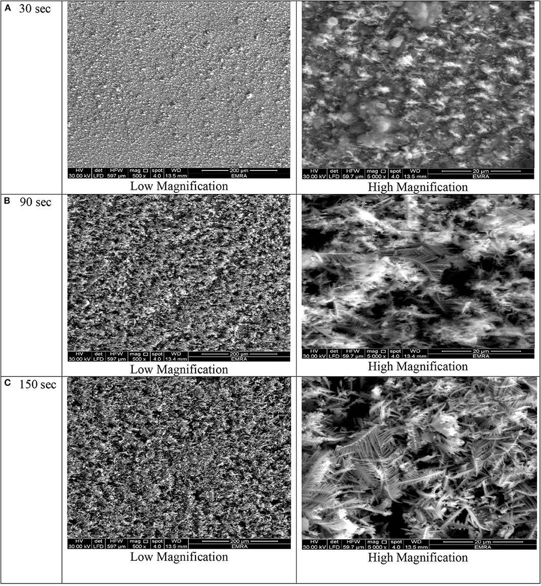
Figure 3. SEM micrographs of porous Ni–Cu layers electrodeposited on AISI 304 stainless steel for (A) 30 s, (B) 90 s, (C) 150 s at current density of 1.5 mA/cm2.
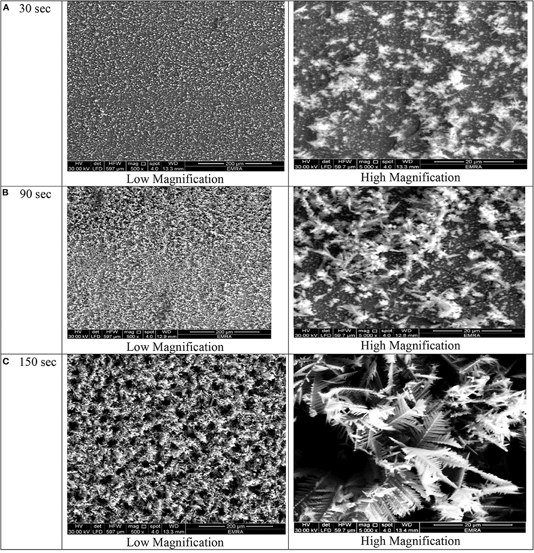
Figure 4. SEM micrographs of porous Ni–Cu layers electrodeposited on AISI 304 stainless steel for (A) 30 s, (B) 90 s, (C) 150 s at current densities of 1.8 mA/cm2.
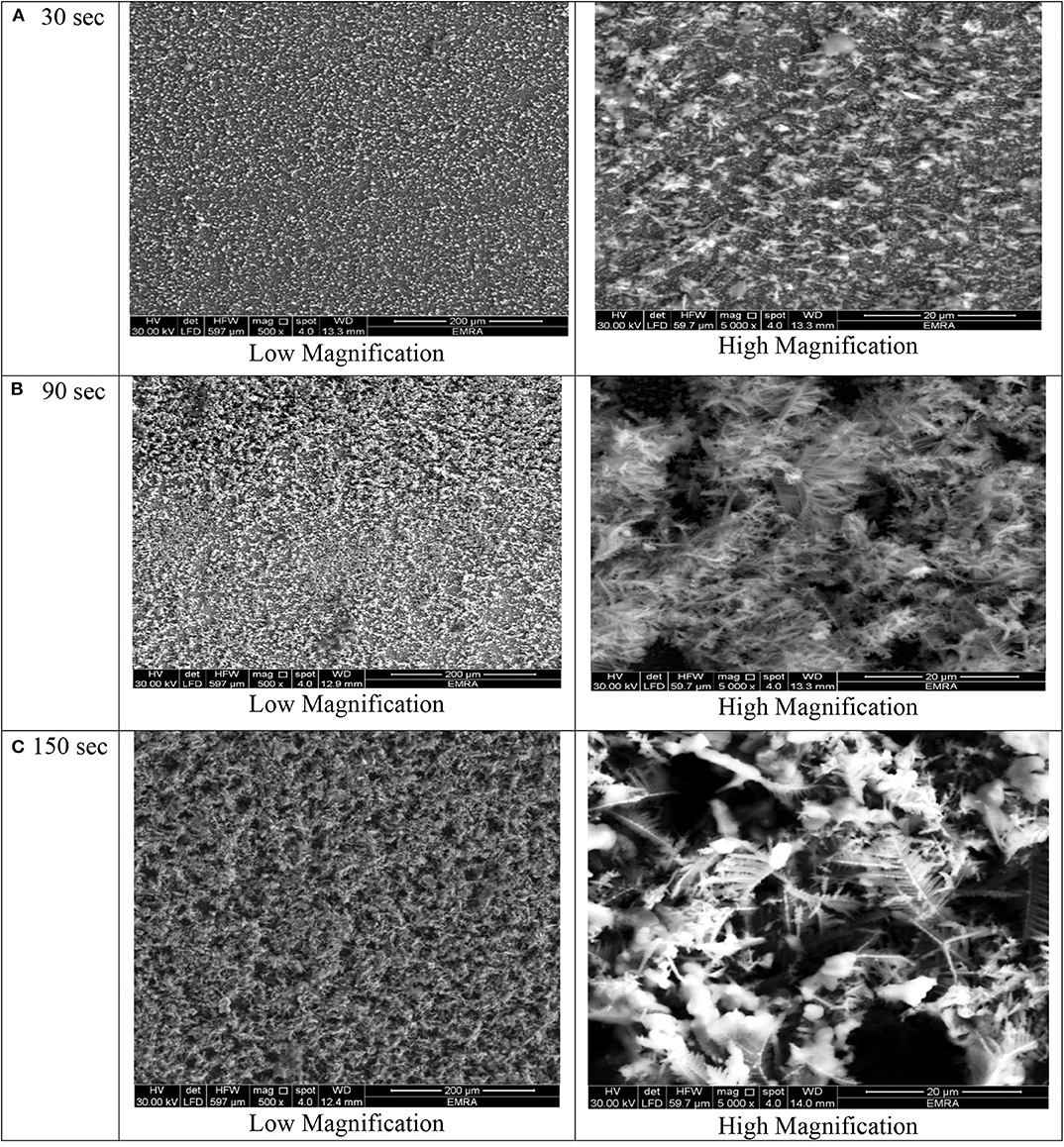
Figure 5. SEM micrographs of porous Ni–Cu layers electrodeposited on AISI 304 stainless steel for (A) 30 s, (B) 90 s, (C) 150 s at current densities of 2 mA/cm2.
Nanostructured metallic foams (NMFs) are three-dimensional (3D) structures of interconnected pores with nano-ramified walls formed of metallic particles, dendrites, or other morphologies that combine good electric and thermal conductivity with high surface area and low density.
By optimizing the electrodeposition parameters, it is possible to produce nano-ramified foam structures with properly tailored architectures to enhance mass and charge transfer processes (Zhang et al., 2014).
At deposition time 30 for all current densities applied, no three-dimensional dendritic structure was formed (Figures 2–5). In these conditions, only rough films composed of angular grains, with few randomly distributed isolated dendrites, are formed.
For longer deposition durations, the resulting films were characterized by dendritic foam-like morphology with randomly distributed nearly circular pores. The most uniform pore morphology was obtained at a current density of 1.8 A/cm2 (Figure 4). Increasing the electrodeposition current density up to 2 A/cm2 leads to the formation of more ramified thinner dendrites (Figure 5). The continuous thin film formed at the substrate's interface was still visible for all samples.
As shown in Figures 2–5 and in agreement with Euge'nio et al. (2014), increasing the deposition time favors the formation of a 3D structure of the foams, due to the increase in the foam thickness and mass. In addition, the longer the deposition time, the coarser pore size to be formed due to the growth of hydrogen bubbles overtime and coalescence of adjacent bubbles (Nikolić et al., 2006a; Abdel-Karim et al., 2019). It can be concluded that the porosity of the metallic foams arises not only from the existence of pores but also due to the open dendritic structure of the pore walls.
From the EDX analysis of porous Ni–Cu electrodeposits presented in Table 3, the layers contained nickel and copper. Residual amounts of oxygen were detected. Based on current density and deposition time, the Ni content ranges from 63.38% up to 81.48%. The corresponding copper content was in the range 18.16–36.62%. The low oxygen content detected indicated the presence of metallic nickel and copper.
In general, increasing both the deposition time and current density leads to an increase in the Cu content in the porous foams.
The potentiodynamic polarization curves of electrodeposited Ni–Cu metallic foams tested in 1 M KOH, as a function of current density, as well as electrodeposition time are illustrated in Figure 6. The corrosion data are summarized in Table 4.
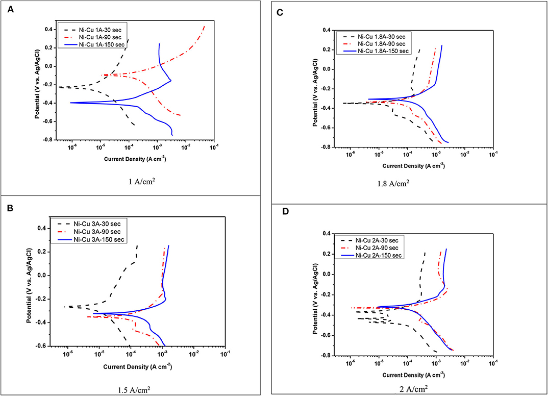
Figure 6. Polarization curves for the corrosion of Ni–Cu foam in 1 M KOH at 25°C. (A) 1 A/cm2, (B) 1.5 A/cm2, (C) 1.8 A/cm2, (D) 2 A/cm2.
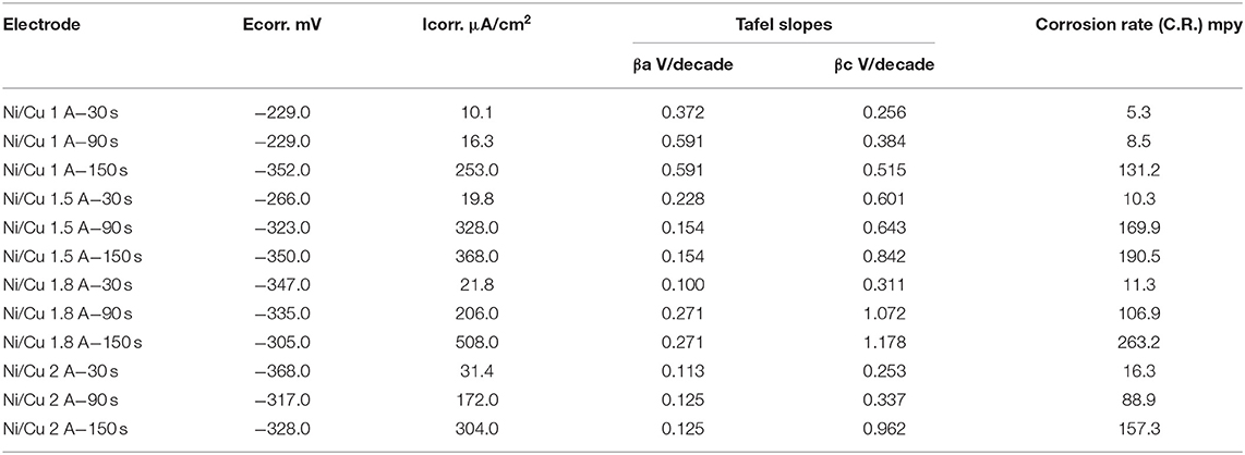
Table 4. Polarization data for the corrosion of electrodeposited Ni–Cu foam at different current densities (A/cm2) and different times (30, 90, 150 s) using 1 M KOH at 25°C.
A shift toward higher anodic and cathodic current densities was detected with increasing electrodeposition time. The corrosion rate was increased by increasing both current density and deposition time. The lowest corrosion rate (5.3 mpy) was registered for porous Ni–Cu layers that were electrodeposited at a current density of 1 A/cm2 for 30 s. In this case, the surface morphology was characterized by rough surface with few dendrites. The surface films in this case contain the highest nickel content (77.67% Ni, 22.33% Cu). The highest corrosion rate (263 mpy) was detected for porous Ni–Cu layers that were electrodeposited using a current density of 1.8 A/cm2 for 150 s. According to EDX analysis, these layers contain 64.98% Ni and 33.55% Cu. Referring to the SEM images, the surface morphology was characterized by the formation of a fine dense ramified dendritic structure.
Figure 7 shows the Nyquist representation data for porous Ni–Cu layers electrodeposited at different deposition times and current densities, using 1 M KOH. The charge transfer process is considered predominantly to control the hydrogen evolution reaction, which is assured by the uni-loop of Nyquist plots (Negem and Nady, 2017). According to previous work (Levie, 1967), the two semicircles appeared at higher current densities (1.8, 2 A/cm2), indicating the formation of pore geometry with dendritic structure.
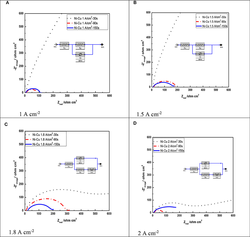
Figure 7. Nyquist plots of Ni–Cu foams tested in acidic 1 M KOH solution as a function of current density as well as electrodeposition time at 25°C. (A) 1 A cm−2, (B) 1.5 A cm−2, (C) 1.8 A cm−2, (D) 2 A cm−2.
From Figure 7, it can be concluded that layers electrodeposited at a longer time showed a smaller arc diameter meaning that they have the lowest impedance to charge transfer (Li et al., 2016). The lowest arc diameter was registered for porous Ni–Cu layers electrodeposited at 2 A/cm2 for 150 s.
Table 5 summarizes the data by fitting EIS experimental recorded at various deposition current densities and times of the investigated porous layers. The solution resistance (Rs) changed in all the experiments by a small degree due to using the same electrolyte. In addition, it can be concluded that the polarization resistance (Rp) decreased as the deposition current density as well as electrodeposition time increased (Sun et al., 2016). The lowest polarization resistance was detected for porous Ni–Cu layers electrodeposited at 2 A/cm2 for 150 s (75.27 ohm).
Figure 8 shows Nyquist plots of Ni–Cu foams tested in 1 M KOH solution as a function of electrodeposition current density at constant deposition time (150 s).
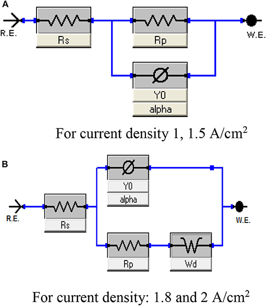
Figure 8. Equivalent circuit represents the behavior of porous Ni–Cu electrodeposited layers in 1 M KOH solution at 25°C. (A) For current density 1, 1.5 A/cm2, (B) For current density: 1.8 and 2 A/cm2.
From Table 5, it is observed that values of polarization resistance decrease with increasing both current density and deposition time. This corresponds to increasing the pore size of Ni–Cu deposits, indicating blocking a fraction of the electrode active surface area by H2 gas bubbles (Yu et al., 2016), preventing the electrolyte access. It can be concluded that porous Ni–Cu electrode, with low Rp (75.27 ohm) value, manifests the highest apparent catalytic activities. This corresponds to the following electrodeposition conditions: 2 A/cm2 current density, 150-s deposition time.
Figure 8 represents the equivalent circuit model of the electrochemical interface used to explain the electrocatalytic activity of the deposited electrode. A common feature of most of the circuits is the presence of the solution resistance (Rs), polarization resistance (Rp), and constant phase elements (CPE) (Figure 9A). Warburg Wd appeared for Ni/Cu 1.8 A/cm2–(30–90–150) s and Ni/Cu 2 A/cm2–(30–90–150) s (Figure 9B).
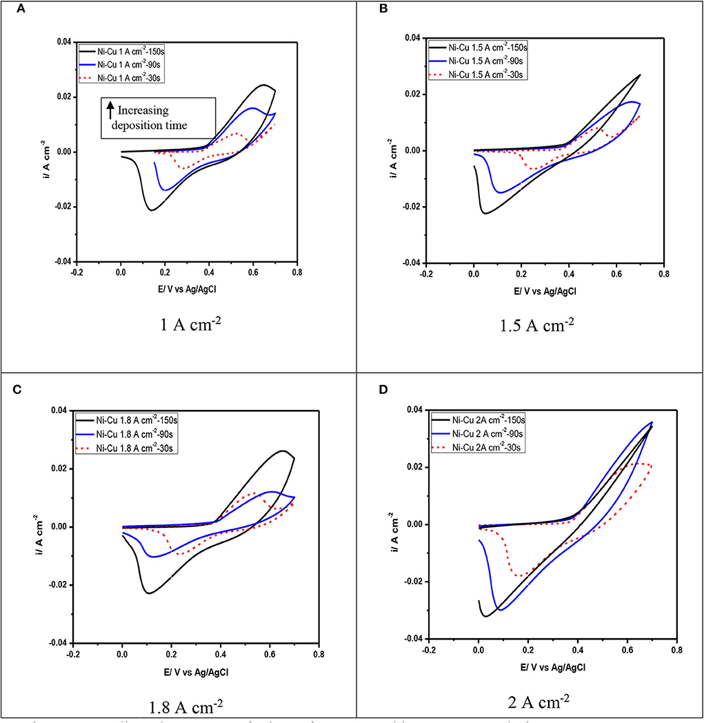
Figure 9. Cyclic voltammetry of Ni–Cu foams tested in 1 M KOH solution at scan rate 75 mV/s. (A) 1 A cm−2, (B) 1.5 A cm−2, (C) 1.8 A cm−2, (D) 2 A cm−2.
Figure 9 illustrates the electrochemical behavior of Ni–Cu foams evaluated in 1 M KOH solution by cyclic voltammetry. These diagrams of Ni–Cu foams represent cyclic voltammetry of materials that are not square shaped as those of materials that exhibit an electric double layer charge storage mechanism (Yu et al., 2013), containing oxidation and reduction peaks that indicate a pseudocapacitive behavior, i.e., charge storage originates from reversible redox reactions. The cyclic voltammetry of Ni–Cu foams have a couple redox peaks in the potential range of −0.2 to +0.8 V. The anodic peak is related to the oxidation reaction of Ni (OH)2 to a higher-valence oxy-hydroxide (NiOOH), while the cathodic peak is associated to the corresponding reduction reaction, following the given equation below (Yau et al., 1994):
The cyclic voltammetry Ni–Cu foams is similar to that reported in the literature for Ni oxides in alkaline solutions (Hu et al., 2008). It can be suggested that the Ni–Cu foams are oxidized upon their immersion in the KOH alkaline solution and potential cycling. In this potential range, copper undergoes one redox reaction Cu (II)/Cu (III) involving CuO surface species (Medina et al., 1978). However, the corresponding voltammetric peak was not detected in the voltammetric curves. It can be concluded that for Cu–Ni alloys, copper oxidation reactions are hindered due to the formation of a protective nickel hydroxide film (Ismail et al., 2004).
The increase in applied current density leads to an increase in the current density obtained during cyclic voltammetry. An increase in the forward peak intensity and total charge measured by cyclic voltammetry has a beneficial effect on the electrochemical activity of the films.
It is also observed that at current densities of 1 and 1.5 mA/cm2, as the deposition time increases, there is an increase in peak separation along with broadening of the peaks observed in the cyclic voltammetry (Figure 9A). High peak separation in the cyclic voltammetry of porous materials is due to both ohmic resistance resulting from the electrolyte diffusion through the pores and polarization of the electrode material (Meher et al., 2011). Therefore, the oxidation currents observed in the Ni–Cu foams for potentials above −0.3 V seem to be mainly attributed to the Cu presence. The highest current peaks were obtained at the Ni–Cu electrode electrodeposited at 2 A/cm2 and 150 s in the whole potential range scanned, which is mainly attributed to the larger area of the Ni–Cu (Figure 9D).
According to Menshykau and Compton (2008), the electrode porosity and morphology can significantly affect the shape of cyclic voltammetry, in particular, the peak current and separation. This is due to the formation of a thin layer of diffusion regime.
The specific capacitance Cs was calculated on the cyclic voltammetry measurements using the following equation:
where, ∫ I dV is the area under the curve
m is the weight gain
v is the scan rate = 75
Δ v equals 1 for KOH electrolyte
where I represents the voltammetric current, m is the total mass of the solid electrode material, v is the potential scan rate, and ΔV is the one sweep subdivision (Mirzaee and Dehghanian, 2018; Mirzaee et al., 2018).
From Table 6, the specific capacitances of 99.2, 149.7, and 211.73 F/g were obtained for Ni–Cu foam at 1, 1.5, and 2 A/cm2 at 30 s. The specific capacitances of 67.9, 31.7, 16.4, and 41.2 F/g were obtained for Ni–Cu foam at 1, 1.5, 1.8, and 2 A/cm2 at 90 s. Notably, an increase in current density resulted in a gradual decrease in discharge Csp values, probably due to the resistance of Ni–Cu foam and the deficient redox reaction at a higher current density. The greatest specific capacitance was obtained at 2 A/cm2 at 30 s. The smallest specific capacitance was obtained at 2 A/cm2 at 150 s, which was the same trend for electrochemical characterization.
According to Mohd Zain et al. (2019), CoCuNi-bdc/NF could be the promising electrode material for supercapacitor materials. The specific capacity of CoCuNi-bdc/NF was ~321.3 mA h g−1, which is over 50% larger than the best performing single metal-terephthalate.
The energy density E was calculated on the cyclic voltammetry measurements using equation (3):
where C depicts the average specific capacitance, and ΔV is the potential extent of one sweep fragment.
Power density P = (E/Δt)*3600
where E is the energy density, and Δt is the period for one sweep fragment = 2.
By calculating both energy and power density, we observed the same trend of energy and power density as that obtained for the specific capacitance. The greatest energy and power density were 29.4 Wh/kg and 52,920 W/kg obtained at 2 A/cm2 at 30 s, respectively. Thus, the electrodes made from the Ni–Cu foam may become an ideal candidate for future use as electrodes for supercapacitors.
• The weight gain due to electrodeposition increased when increasing both the deposition time as well as deposition current density. Samples electrodeposited at 1.8 A/cm2 showed a remarkable low weight gain. This might be due to high porosity of the layer deposited at 1.8 A/cm2.
• Deposition time 30 for all current densities applied fails to produce three-dimensional structures of porous Ni–Cu foams. As the deposition time increases, dendrites assume a fern-like structure with secondary and tertiary branching maintaining a non-compact pore wall.
• In general, according to EDX analysis, increasing both the deposition time and applied current density leads to increasing the Ni content in the nanofoams.
• The highest corrosion rate (263 mpy) was detected for porous Ni–Cu layers that were electrodeposited at a current density of 1.8 A/cm2 for 150 s. The surface morphology was characterized by the formation of fine dense ramified dendritic structure.
• The Ni–Cu foams presented a pseudocapacitive behavior and charge storage arising from reversible redox reactions of the Ni–Cu electrodeposited layer.
• A maximum specific capacitance value of 211.73 F/g at 2 mA/cm2 and deposition time 30 s were obtained.
• From the EIS test, the polarization resistance (Rpo) decreased as the current density as well as electrodeposition time increased. The lowest polarization resistance was recorded for porous Ni–Cu layers electrodeposited at 2 A/cm2 for 150 s (1 ohm).
The datasets generated for this study are available on request to the corresponding author.
RA-K: construction of research methodology and text preparation. AA: electroplating process and follow up of SEM capturing. KZ: electrochemical characterization techniques. YR: electroplating process. SE-R: discussion of results and conclusions. All authors contributed to the article and approved the submitted version.
This work was funded by Cairo University Grants—Egypt for Scientific Research 2017–2019.
The authors declare that the research was conducted in the absence of any commercial or financial relationships that could be construed as a potential conflict of interest.
Abdel-Karim, R., Reda, Y., Zohdy, K., Abdelfatah, A., and El-Raghy, S. (2019). Electrochemical performance of porous Ni-Cu anodes for direct methanol fuel cells. Int. J. Electrochem. Sci. 14, 3035–3054. doi: 10.20964/2019.03.59
An, K., Kim, W., Park, Y., Jeong, H. J., Choi, Y. C., Moon, J. M., et al. (2001). Supercapacitors using single-walled carbon nanotube electrodes. Adv. Mater. 13, 497–500. doi: 10.1002/1521-4095(200104)
Arbizzani, C., Mastragostino, M., and Soavi, F. (2001). New trends in electrochemical supercapacitors. J. Power Sources. 100, 164–170. doi: 10.1016/S0378-7753(01)00892-8
Arico, A. S., Bruce, P., Scrosati, B., Tarascon, J. M., and Schalkwijk, W. V. (2005). Nanostructured materials for advanced energy conversion and storage devices. Nat. Mater. 4, 366–377. doi: 10.1038/nmat1368
Brinker, C. J., Frye, G. C., Hurd, A. J., and Ashley, C. S. (1991). Fundamentals of sol-gel dip coating. Thin Solid Films 201, 97–108. doi: 10.1016/0040-6090(91)90158-T
Burke, A. (2000). Ultra capacitors: why, how, and where is the technology. J. Power Sources 91, 37–50. doi: 10.1016/S0378-7753(00)00485-7
Cardoso, D. S. P., Eug'enio, S., Silva, T. M., Santos, D. M. F., Sequeira, C. A. C., and Montemor, M. F. (2015). Hydrogen evolution on nanostructured Ni–Cu foams. RSC Adv. 5, 43456–43461. doi: 10.1039/C5RA06517H
Conway, B. E. (1999). Electrochemical Supercapacitors Scientific Fundamentals and Technological Applications. New York, NY: Plenum Press.
Euge'nio, S., Silva, T., Carmezim, M., Duarte, R., and Montemor, M. (2014). Electrodeposition and characterization of nickel–copper metallic foams for application as electrodes for supercapacitors. J. Appl. Electrochem. 44, 455–465. doi: 10.1007/s10800-013-0646-y
Herraiz-Cardona, I., González-Buch, C., Ortega, E., García-Antón, J., and Pérez-Herranz, V. (2013). Energy efficiency improvement of alkaline water electrolysis by using 3D Ni cathodes fabricated via a double-template electrochemical process. Chem. Eng. Transac. 32,451–456. doi: 10.3303/CET1332076
Hu, C., Chang, K., and Hsu, T. (2008). The synergistic influences of OH− concentration and electrolyte conductivity on the redox behavior of Ni (OH)2/NiOOH. J. Electrochem. Soc. 155, 196–200. doi: 10.1149/1.2945911
Ismail, K., Fathi, A., and Badawy, W. (2004). The influence of Ni content on the stability of copper–nickel alloys in alkaline sulphate solutions. J Appl. Electrochem. 34, 823–831. doi: 10.1023/B:JACH.0000035612.66363.a3
Levie, R. (1967). “Electrochemical responses of porous and rough electrodes,” in Advances in Electrochemistry and Electrochemical Engineering, eds P. Delahay and C. W. Tobias (New York, NY: Interscience), 329–397.
Li, W., Liu, J., and Zhao, D. Y. (2016). Mesoporous materials for energy conversion and storage devices. Nat. Rev. Mater. 1:16023. doi: 10.1038/natrevmats.2016.23
Medina, A., Marciano, S., and Arvia, A. (1978). The potentiodynamic behaviour of copper in NaOH solutions. J. Appl. Electrochem. 8, 121–134. doi: 10.1007/BF00617670
Meher, S., Justin, P., and Rang, G. (2011). Nanoscale morphology dependent peseudocapacitance of NiO. influence of intercalating anions during synthesis. Nanoscale 3, 683–692. doi: 10.1039/C0NR00555J
Menshykau, D., and Compton, R. (2008). The influence of electrode porosity on diffusional cyclic voltammetry. Electroanalysis 20, 2387–2394. doi: 10.1002/elan.200804334
Mirzaee, M., and Dehghanian, C. (2018). Nanostructured Ni-Cu foam electrodeposited on a copper substrate applied as supercapacitor electrode. Acta Metallurg. Slovaca 24, 325–336. doi: 10.12776/ams.v24i4.1138
Mirzaee, M., Dehghanian, C., and Bokati, K. S. (2018). ERGO grown on Ni-Cu foam frameworks by constant potential method as high performance electrodes for supercapacitors. Appl. Surf. Sci. 436, 1050–1060. doi: 10.1016/j.apsusc.2017.12.145
Mohamed, A., Abdel-Karim, R., Zohdy, K., and El-Raghy, S. (2019). Electrocatalytic activities of macro- porous nickel electrode for hydrogen evolution reaction in alkaline. Egypt. J. Chem. 62, 1065–1078. doi: 10.21608/ejchem.2018.5017.1443
Mohd Zain, N. K., Vijayan, B. L., Misnon, I. I., Das, S., Karuppiah, C., Yang, C.-C., et al. (2019). Direct growth of triple cation metal-organic framework on a metal substrate for electrochemical energy storage. Ind. Eng. Chem. Res. 58, 665–674. doi: 10.1021/acs.iecr.8b03898
Nam, D., Kim, R., Han, D., Kim, J., and Kwon, H. (2011). Effects of (NH4)2SO4 and BTA on the nanostructure of copper foam prepared by electrodeposition. Electrochim Acta 56, 9397–9940. doi: 10.1016/j.electacta.2011.08.025
Negem, M., and Nady, H. (2017). 'Electroplated Ni-Cu nanocrystalline alloys and their electrocatalytic activity for hydrogen generation using alkaline solutions. Int. J. Hydr. Energy 42, 28386–28396. doi: 10.1016/j.ijhydene.2017.09.147
Nikolić, N. D., Popov, K. I., Pavlović, L. J., and Pavlović, M. G. (2006a). Morphologies of copper deposits obtained by the electrodeposition at high overpotentials. Surf Coat Technol. 201, 560–566. doi: 10.1016/j.surfcoat.2005.12.004
Nikolić, N. D., Popov, K. I., Pavlović, L. J., and Pavlović, M. G. (2006b). Phenomenology of a formation of a honeycomb-like structure during copper electrodeposition. J. Solid State Electrochem. 11, 667–675. doi: 10.1007/s10008-006-0222-z
Santos, D. M. F., Eugénio, S., Cardoso, D. S. P., Šljukić, B., and Montemor M, F. (2015a). Three-dimensional nanostructured Ni–Cu foams for borohydride oxidation. Russ. J. Phys. Chem. A 89, 2449–2454. doi: 10.1134/S0036024415130336
Santos, D. M. F., Eugenio, S., Sequeira, C. A. C., and Montemor, M. F. (2015b). Transition metal foam electrocatalysts for hydrogen evolution reaction. ECS Trans. 64, 9–16. doi: 10.1149/06429.0009ecst
Shin, H.-C., and Liu, M. (2004). Copper foam structures with highly porous nanostructured walls. Chem Mater. 16, 5460–5464. doi: 10.1021/cm048887b
Shin, H. C., Dong, J., and Liu, M. (2013). Nanoporous structures prepared by an electrochemical deposition process. Adv Mater. 15, 1610–1614. doi: 10.1002/adma.200305160
Sun, T. T., Xu, L. B., Li, S. Y., Chai, W. X., Huang, Y., Yan, Y. S., et al. (2016). Cobalt-nitrogen-doped ordered macro-/mesoporous carbonfor highly efficient oxygen reduction reaction. Appl. Catal. B Environ. 193, 1–8. doi: 10.1016/j.apcatb.2016.04.006
Tan, K., Tian, M.-B., and Cai, Q. (2010). Effect of bromide ions and polyethylene glycol on morphological control of electrodeposited copper foam. Thin Solid Films 518, 5159–5163. doi: 10.1016/j.tsf.2010.03.029
Yau, S., Fan, F., Moffat, T., and Bard, A. (1994). In situ scanning tunneling microscopy of Ni (100) in 1 M NaOH. J. Phys. Chem. 98, 5493–5499. doi: 10.1021/j100072a016
Yu, A., Chabot, V., and Zhang, J. (2013). Electrochemical Supercapacitors for Energy Storage and Delivery, 1st Edn. Boca Raton, FL: CRC Press.
Yu, L., Lei, T., Nan, B., Jiang, Y., He, Y., and Liu, C. (2016). Characteristics of a sintered porous Ni–Cu alloy cathode for hydrogen production in a potassium hydroxide solution. Energy 97, 498–505. doi: 10.1016/j.energy.2015.12.138
Zaharaddeen, S., Iro, C., and Subramani, S. (2016). Short review a brief review on electrode materials for supercapacitor. Int. J. Electrochem. Sci. 11, 10628–10643. doi: 10.20964/2016.12.50
Keywords: nickel–copper thin films, nanostructured foams, dynamic hydrogen bubble templating (DHBT) technique, supercapacitors, specific capacitance, energy density
Citation: Abdelfatah A, Reda Y, Abdel-Karim R, El-Raghy SM and Zohdy KM (2020) Electrochemical Characterization of Electrodeposited Ni–Cu Foams and Their Application as Electrodes for Supercapacitors. Front. Mech. Eng. 6:35. doi: 10.3389/fmech.2020.00035
Received: 08 February 2020; Accepted: 08 May 2020;
Published: 26 June 2020.
Edited by:
Rodrigo Sávio Pessoa, Aeronautics Institute of Technology (ITA), BrazilReviewed by:
Vijaykumar Jadhav, University College Cork, IrelandCopyright © 2020 Abdelfatah, Reda, Abdel-Karim, El-Raghy and Zohdy. This is an open-access article distributed under the terms of the Creative Commons Attribution License (CC BY). The use, distribution or reproduction in other forums is permitted, provided the original author(s) and the copyright owner(s) are credited and that the original publication in this journal is cited, in accordance with accepted academic practice. No use, distribution or reproduction is permitted which does not comply with these terms.
*Correspondence: Randa Abdel-Karim, cmFuZGFhYmRlbGthcmltQGdtYWlsLmNvbQ==
Disclaimer: All claims expressed in this article are solely those of the authors and do not necessarily represent those of their affiliated organizations, or those of the publisher, the editors and the reviewers. Any product that may be evaluated in this article or claim that may be made by its manufacturer is not guaranteed or endorsed by the publisher.
Research integrity at Frontiers

Learn more about the work of our research integrity team to safeguard the quality of each article we publish.