- DIMEAS-Department of Mechanical and Aerospace Engineering, Politecnico di Torino, Turin, Italy
This paper deals with the problem of compliance in biped robots locomotion. After a first literature review, we designed and simulated a 3D virtual model of a biped robot conceived with the same link dimensions (and weights) of a standard man. In all simulation, the same input to the robot actuators are proposed, modifying only the compliance of the attached links. We first validated the model and then compared results increasing and reducing compliance on hip, knee and ankle joints. The very good results underline how the robot performances may be increased including the compliant element in the knee. In particular, we noted how including a proper value of the compliance in the knee, power and torque of the actuators may be reduced increasing robot speed.
1. Introduction
Humanoid robots are conceived with the final objective to have a human-like behavior. Biped robots are normally composed of rigid bodies linked by simple kinematic connections. The segments of the human body are not rigid and this difference between human and robot produces many discrepancies in their dynamic balance. The lack of compliance systems in biped robots may transfer high loads to the whole structure due to the impact of the robot feet with the ground. The correct distribution of the ground reaction forces from the ground to the robot structure is important in order to avoid damages on the actuators during the robot gait. In the meanwhile, the compliance systems help to increase robot performances thanks to their capabilities to absorb impacts and transfer energy.
Collins et al. developed a passive-dynamics based bipedal walking robot with the aim of minimizing energy consumption to reach the same mechanical energy efficiency of human walking (Collins et al., 2001; Collins and Ruina, 2005). Some authors proposed the use of antagonistic pneumatic actuators for changing the joint compliance in order to perform three dynamic locomotion modes: walking, running and jumping (Hosoda et al., 2006). In Schauss et al. (2009), the addition of compliant ankles and the application of hybrid zero dynamics method provided a great result toward human-like gait applied to a seven link robot. In Muscolo and Recchiuto (2017), the authors present a creative design approach in order to simplify biped locomotion of humanoid robots. In order to obtain a humanlike motion on a planar surface, they developed a bipedal humanoid robot with two legs, constituted by a passive flexible structure and using only two motors on the feet equipped with wheels (Muscolo et al., 2017a,b). Jerry Pratt and Benjamin Krupp introduced the concept of series elastic actuators (SEA) and how they can be implemented in robots who operate in unconstrained environments (Pratt and Krupp, 2004). Other researchers in Sensinger et al. (2013) show their studies on the effect of compliance location in SEAs. The work in Zhou et al. (2015) introduced a local stabilization strategy based on active compliance control. The scope of the work is to stabilize, with active stiffness and damping regulation, an intrinsically compliant humanoid system during locomotion. The control strategy was validated on a real humanoid robot COMAN (COMpliant huMANoid). In Song et al. (2013), some researchers investigated the source of energy reduction derived from the implementation of windlass mechanism. They focused their attention on feet compliance as one of the functionalities that windlass mechanism embeds. The results have shown that compliant feet require more energy than stiff feet during a walk. In Hurst et al. (2016), the use of mechanical springs that allow to reduce the power requirements of actuators, to store and release energy when it is necessary and to prevent collision impacts due to interactions with the environment are shown. The work proposed in Muscolo et al. (2013) modifies the compliance of the humanoid arm, DEXTER, an eight DOFs manipulator, modifying the software parameters. Simulations show that by varying the stiffness of the environment, with a variation of the software parameters, both control systems ensure the achievement of the desired force and position. The aim of the work Endo et al. (2006) is to demonstrate that a quasi-passive leg structure can reach a human-like walking without knee and ankle actuator but using only a single actuator at hip's joint. The model of leg structure consists of knee and ankle passive and quasi-passive elements, including springs, clutches and variable dampers. In Wisse et al. (2006), the authors demonstrate that spring stiffness has a positive effect on the reaction to external disturbance as well as arc radius of arc-shaped feet. In Guihard and Gorce (2004), the authors proposed a biorobotic foot model based on pneumatic actuation type and designed with a dynamic behavior as close as possible to human one. The work of Iida et al. (2008) presents a minimalistic bipedal locomotion model with a compliant leg structure that is able to perform both walking and running gaits. Through simulations, the authors show how the proposed model agrees with the basic principles of human locomotion. The authors in Geyer et al. (2006) show how compliant legs are essential to obtain the basic walking mechanics. The authors of Li et al. (2008) developed a new flexible foot with rubber bushes and rubber pads for absorbing impacts with the ground and equipped with a real-time attitude estimation system. The work of Torricelli et al. (2016) presents a synthetic view of biomechanical principles of human walking and it deals with biomechanical compliance as one of the key properties of human systems. The work of Wu et al. (2018) aims at investigating the effects of ground compliance on flexible planar passive biped dynamic walking based on continuous force method. The aim of the research work of Kim (2013) is to analyse the work at the joint space of compliant legs for bipedal walking robots. Some researchers in Tsagarikis et al. (2010) presented the design and realization of a new variable compliance actuator for robots physically interacting with humans that can control the stiffness using two motors. In the review work of Ham et al. (2009) the state of the art in the design of actuators with passive adjustable compliance/controllable stiffness for robotic applications is described. The authors demonstrated in Zelik et al. (2014) how ankle elasticity can aid walking economy by redirecting CoM, reducing collisions.
In a recent work (Schrade et al., 2019), the authors investigated how a variable stiffness actuator at the knee joint influences collision forces transmitted to the user via the exoskeleton. In Li et al. (2019), a compliant crank-slider mechanism can be constructed by adding constant-stiffness springs at its joints. In Baček et al. (2020), the authors analyzed the effects that changing mechanical compliance has on the actuator's overall performance in different ideal conditions in an experimental test setup.
The field of compliant walking is very important to minimize shock loads, derived from foot impact with the ground, employing compliant mechanisms in order to reduce the impact forces. Reducing interface stiffness offers a number of advantages, including greater shock tolerance, more accurate and stable force control, and the capacity for energy storage.
The authors, in the work of Hashimoto et al. (2012), developed a walking stabilization control to stabilize the center of mass (CoM) motion in the lateral direction on a soft ground. After a first analysis of the work of Hashimoto et al. (2012), in order to study the interaction of a robot without compliant joints, but with a soft ground, we found the convenience to include the soft element inside the robot joint. In this paper, the authors show how the introduction of a knee compliant joint can improve the behavior of the biped robot at the impact with the ground. In our biped robot model, we have realized a variable stiffness joint in which the compliant element is not combined with the actuator, in this way, the decoupling between the connection line of the links and the actuator let us to minimize impulsive loads, derived from impact with the ground, to which the actuator is subjected. Through simulations of walking and running, we have evaluated the benefits gained from this type of joint.
The paper is structured as follows: Section 2 shows our virtual robot model developed with Matlab; section 3 presents the joint motion input profile; section 4 shows the validation of our prototype including implementation, results and discussion. The paper ends with conclusion.
2. Virtual Robot Model Design
2.1. Multibody Model
Simscape Multibody (a Matlab's tool) provides a multibody simulation environment for 3D mechanical systems, in order to model multibody systems using blocks representing bodies, joints, constraints, force elements, and sensors. In this paper, we introduce the simulation model of a biped robot in Simscape Multibody. The robot model consists of 14 different types of bodies and six revolute joints with one rotational degree of freedom each, located at the hip, knee and ankle. A compression spring is interposed between each link in such a way that we can change its stiffness value regardless of the task carried out by the robot. For anthropometric characteristics, the standard man (age 30; height: 1,720 mm; mass: 70 kg) has been used as a virtual reference model for the simulation (Muscolo et al., 2017b).
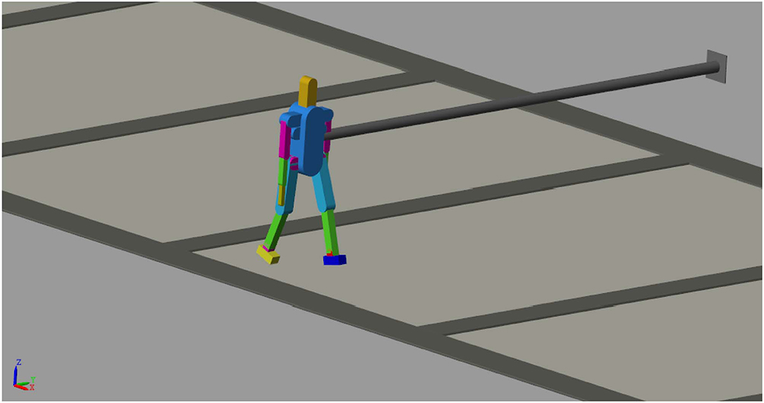
Figure 1 shows the model structure. In order to run out tests we fixed the biped robot trunk to a wall allowing two degrees of freedom in the ZX plane. In this mode the trunk is free to move in X and Z direction and only Y rotation is avoided in the ZX plane. The virtual robot model with these constraints allows to evaluate the influence on the compliant joints during walking and running avoiding the disturb of the balancing during locomotion.
2.2. Foot-Ground Contact Modeling
In the model designed in this paper, the behavior of the contact of the foot with the ground was realized with the Simscape Multibody Contact Forces Library which provides contact force models for intermittent contact (Miller, 2020). In order to achieve a correct contact between the parts in the system that hit each other during simulation, a general approach was used:
1. Identify the parts in the system that will hit each other during simulation.
2. Figure out which edges or surfaces will touch.
3. Add reference frames for the lines and arcs that will touch.
4. Add contact force model between the two frames.
The block, used to design ground reaction forces during gait, implements a linear force law between a sphere and a plane with specific stiffness and damping parameters. For a given walking gait, we have implemented a Stick-Slip Continuous friction law which allows the biped platform to perform the expected motion. Parameters for the friction forces which act between the foot and the ground are the following: Coefficient of Kinetic Friction = 0.6; Coefficient of Static Friction = 0.8; Velocity Threshold (m/s) = 0.01.
2.3. Variable Stiffness Joint Modeling
Figure 2 shows the sketch of the working principle of the variable stiffness joint implemented in the biped robot model. This joint consists of two compression springs (K1 and K2) interposed between each link and their connection to the revolute joint. Figure 2A shows the case in which the link 1 is fixed to the frame and three DoFs are available (shown with arrows in the picture). If the rotation of the revolute joint is avoided, and the motion of the two links is permitted only in Z direction, the model may be approximated with two springs (K1 and K2) and two masses (m1 and m2) (Figure 2B). If the link 2 of the Figure 2B is blocked (such us in Figure 2C), 1 DoF is available and the system may be represented with a mass (m1) connected with two springs in parallel (K1 and K2).
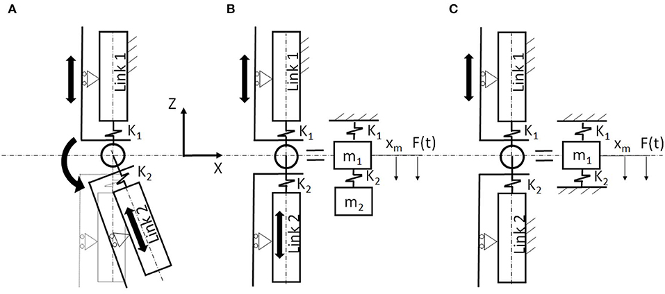
Figure 2. Sketch of the working principle of the variable stiffness joint implemented in hip, knee, and ankle joints on the sagittal plane: (A) link1 is fixed (3 DoFs); (B) rotation is avoided (if link 1 is fixed) (2 DoFs); (C) two links are fixed and rotation is avoided (1 DoF).
In this work, we used the system of the Figure 2A modifying K1 (as shown later), giving an input to the revolute joint which is connected to the actuation and using a high value of stiffness for K2.
2.4. Variable Stiffness Joint Damping Coefficient
Due to high accelerations, the system requires viscous damping in order to dampen the vibrations induced during the biped gait. An elastomeric anti-vibration mount was used on the robotic platform (instead of each spring shown in Figure 2). From Homberger (2018) of chucking and anti-vibrating systems, we have selected the type of anti-vibration mount for our application.
The maximum stress, corresponding to a compression load of 700N, causes a displacement equal to 8mm.
From which, approximating the hysteresis curve of the anti-vibration mount with the linear law of Hooke, we obtain:
The Poisson's ratio of this material is equal to 0.5, so we can calculate the shear modulus, denoted by G which is defined as the ratio of shear stress to the shear strain, but it is also related to the modulus of rigidity, Young's modulus and Poisson's ratio with the following relation:
We proceed with the calculation of the average shear deformation:
where:
χ is the cutting factor and is equal to for circular sections;
T is the shear stress;
G is the shear modulus;
A is the area of the circular section.
The average variation of the viscous damping factor as a function of the shear deformation, we can obtain the ratio between the damping factor and the damping factor with unit average deformation.
From which:
Starting from the critical damping c, we proceed with the calculation of the damping coefficient β:
with: m = 70Kg and . Damping coefficient is equal to:
3. Joint Motion Input Profile
3.1. Walking and Running Gaits
According to the reciprocal contact of one leg and the ground, a classical human gait cycle is composed by stance, where the foot is on the ground, and swing. Stance can be subdivided into four sub-phases: (i) loading response, in which both limbs are in contact with the ground, (ii) mid stance, starting at contralateral toe off, (iii) terminal stance, starting at heel rise and (iv) pre swing, in which, again, both limb are in contact with the ground. With respect to the timing, the gross normal distribution of the floor contact periods is 60% for stance and 40% for swing. Timing for the phases of stance is 10% for each double stance interval (loading response and pre swing) and 40% for single limb support. The precise duration of these gait cycle intervals varies with the person's walking velocity: increasing velocity increases total stance and swing times, while lengthens single stance and shortens the two double stance intervals.
Using the same multibody model presented in Figure 1, we developed two different Robot models (model I and II) and performed for each one the walking and running gait. A total of four gaits have been performed:
1. Robot model I walking gait
2. Robot model I running gait
3. Robot model II walking gait
4. Robot model II running gait.
The difference between the two Robot models (I and II) is based on the difference on the used ankle input. Robot model I uses as input the data of classical human gait in walking and running. The Robot model II uses the same data of the Robot model I except for the ankle joint in walking and running. The Robot model I reproduces the locomotion of a human; the robot model II reproduces the motion of the human during walking and running with the constraint to have the sole of the foot always parallel to the ground. This type of locomotion is the same of the motion that could be reproduced by a robot which uses the Zero Moment Point (ZMP) approach (see Muscolo et al., 2015).
We have actuated the joint primitive of each revolute joint in inverse dynamics mode by providing motion as input while force/torque actuation was automatically computed. The motion input of a joint primitive is a time-series object specifying that primitive's trajectory. For a revolute primitive, the trajectory is the angle about the primitive axis, given as a function of time. This angle provides the rotation of the follower frame with respect to the base frame about the primitive axis.
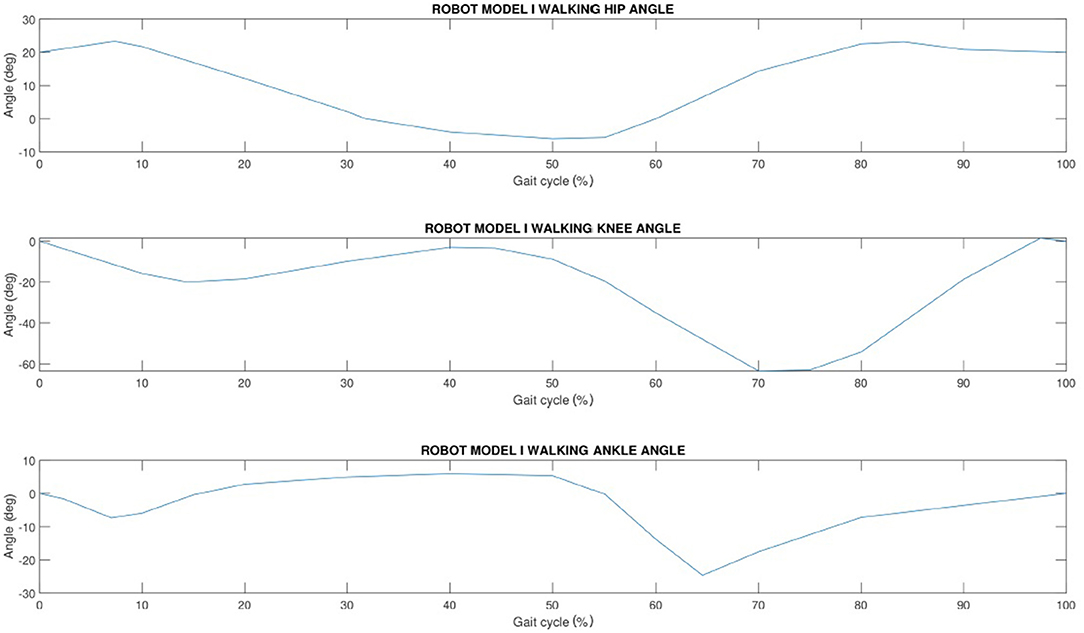
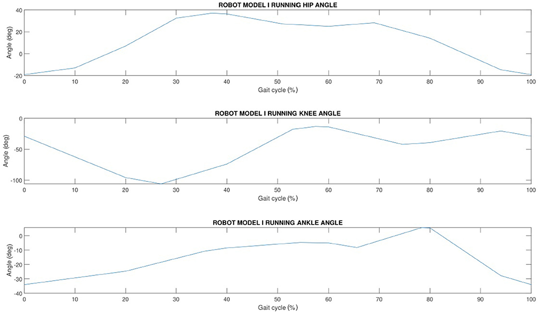
The progression of hip, knee and ankle angle is shown normalized to a gait cycle. Figure 3 shows human hip, knee and ankle joint characteristics at normal walking speed and Figure 4 shows the same angles for human running gait cycle.
Figures 5, 6, show joint ankle angles for Robot model II, respectively, during walking and running gait. The hip and knee walking and running input angles are the same of the Robot model I shown in Figures 3, 4. With the aim of reproducing a walking gait for the Robot model II with the sole of the foot always parallel to the ground, values of ankle angles were calculated based on the following equation:
3.2. Joint Compliance
The current study aims at evaluating to what extent the stiffness of each joint, individually taken, can be optimized to minimize energy. We present a study to demonstrate that the use of our variable stiffness actuator concept can greatly reduce energy expenditure in actuator power.
For the four different tasks performed by the virtual biped robot model, we have set the stiffness value K1, giving to K2 the infinite stiffness (see Figure 2A). Each stiffness value refers to a permitted displacement value, calculated with respect to the total weight of the biped multibody model equal to 70 kg.
For example, the stiffness value indicated with the following expression Rk1 refers to a stiffness value relative to the knee joint with the allowed displacement of 1 millimeter when a force equal to the total weight of the biped humanoid robot is imposed. With the allowed displacement of: x1 = 1mm and x8 = 8mm, we obtain the following stiffness values for the knee with the weight of ; ; .
4. Validation, Implementation, Results, and Discussion
4.1. Model Validation
In order to validate our models, the virtual robot should be compared with the real system. However, in our case, no real robotic systems are available. If the same input of the Figure 3 are included in our model I, and if the stiffness K1 has a high value, the Figure 7, which represents the CoM speed graph, is obtained. It may be noted how the mean value of the CoM speed of the model I is approximately 0.9 m/s during walking gait. This first result gives only an idea of how our virtual robot performances are in line with the human's one, which has the walking speed from 0.5 m/s to 2.6 m/s (Grimmer and Seyfarth, 2014). However, analysing the torques output of our models, with the ones of the human with the same input, we noted that the obtained torques on the knee, hip and ankle joints of our models are not realistic and we discovered the reason of it optimizing results. In particular, if we give the input of the Figures 3–6, the software tries to cover the input creating high accelerations and then high torques. For these reasons, we included torques input instead of kinemtatic ones, which generate the same kinematic of Figures 3–6 but as output. Figure 8 shows the comparison between the kinematic input of the Figure 3 and the kinematic output obtained giving the torque to the joints as input. With this novel input, we reduced the maximum peak torques in the joints and the speed of our model is from around 0.9 m/s (from the Figure 7) to around 0.6 m/s, which may be optimized in future works.
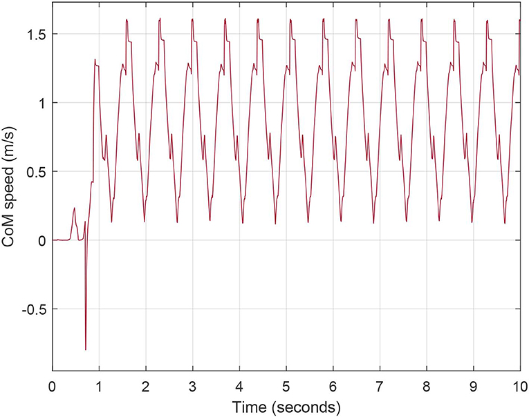
Figure 7. Speed of the Center of Mass (CoM) of the Robot model I walking gait with infinite stiffness joints.
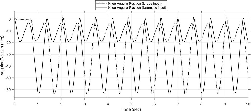
Figure 8. Comparison between kinematic input of the Figure 3 and kinematic output giving torques as input.
4.2. Best Location of the Compliant Element
In the following graphs, these values have been used:
A cross analysis was carried out in order to evaluate how the impact with the ground affects the joints in terms of torque and power required. Each test was performed implementing the compliant element in one joint (hip, knee, or ankle) with different stiffness values, while the other joints have infinite stiffness. This cross analysis let us to check what is the best location of the compliant element and what are the effects it generates on the other rigid joints. The obtained values refer to the bandwidth of the signals measured on the Simscape model through sensors arranged on the biped and they represent the maximum absorption peaks, linked to the impact with the ground, of the measured variable.
With our research we noted that the best location of the compliant element is in the knee joint as it brings greater benefits to the other joints by reducing the peaks due to the impact with the ground. For this reason, from now, we will only consider the knee joint with the compliant element and we will try to optimize, from a performance point of view, a system so configured.
4.3. Compliant Knee Joint
In order to optimize our research, we used two equivalent stiffness values resulting from the series of compliant elements whose stiffness is set to Kc = 87, 500N/m. In particular, a series of three compliant elements with stiffness equal to Kc, provides an equivalent stiffness value of , while a series of five compliant elements gives an equivalent stiffness value of .
Figure 9 compares the two used models (Model I and Model II) during walking and using three different stiffness values for K1:Ka, Kb, and Kc. In 10 s, if K1 = Ka (or K1 = Kb) the CoM of the Model I travels a distance of minus than 5 m; on the contrary, using K1 = Kc the travelled distance is more than 5 m. It is possible to note how the performances of the Model II are inferior respect to the ones of the Model I. For this reason, in the following graphs, only the Model I will be shown. In Supplementary Material, we included two videos of the robot models I and II during walking and running.
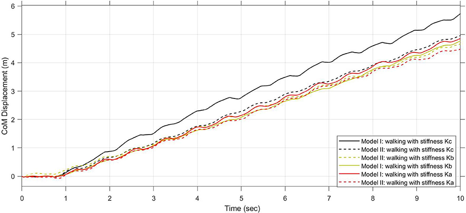
Figure 9. Comparison of performances between Model I and Model II, during walking and using different stiffness value for K1 : Ka, Kb, and Kc.
4.4. Performance Advantages in Running Gait
The compliant element in the knee joint optimizes the biped running by adjusting stiffness values of the variable stiffness joint. If we consider the following stiffness values: ; ; , and the same damping in all the simulations equal to ; we obtain the following results from simulations:
From Figure 10, we can notice that a lower stiffness allows the robot to go further. In fact with a stiffness value of 17, 500N/m, it can travel a distance of about 25 m in 10 s (of simulation). This confirms how a compliant element in the knee joint let us to obtain better performance with a significant reduction in energy expenditure.
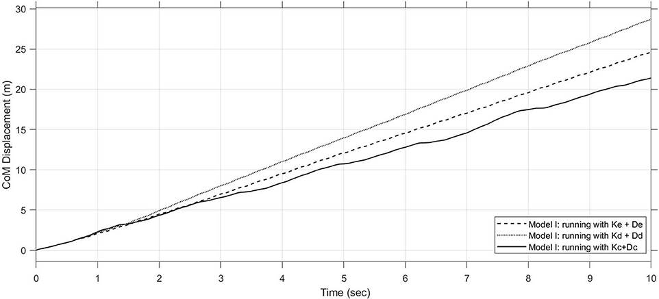
Figure 10. Comparison of performances using Model I during running and using different stiffness and damping values for K1 : Kc + Dc, Kd + Dd, and Ke + De.
If we observe the torque and power trends at the robot joints as a function of the compliant element stiffness value in the knee joint, we can notice that for the stiffness value corresponding to Kd with presence of damping, we are close to an absolute minimum both for walking and running gait. From this observation it can be deduced how the optimization procedure can converge in a first approximation to this value which constitutes a great value with regard to the minimization of torque and power at the impact with the ground and the increase in performance. Another indicator that shows how the optimization procedure has almost reached convergence toward an ideal value of stiffness is shown in Figure 10, where using kd a travelled distance of more than 25 m in 10 s of simulation may be reached. On the other hand, there is a greater difference in the final CoM displacement depending on the use of a stiffness equal to Kd or one equal to Kc because we have a percentage change of about 54%. This means that if we continue to reduce stiffness, we will get smaller percentage changes that will not bring about substantial differences in robot gait. From this optimization approach, we have almost reached an asymptotic convergence with the value of Kd = 29166.67N/m. It would be useless to go down to lower values because we will get percentage changes in final CoM displacement less than 5%.
5. Conclusion
The compliant elements, included in biped legs, may increase the robots' performances. However, the correct combination and position of the compliant elements is not simple to define for many reasons (such as complexity of the multibody model, nonlinearity of the contact point definition, etc.). The results we presented in this work underline how a first step forward in the increasing biped robot performances in locomotion is possible to pursued. In particular, the robot performances are increased more including the compliance in the knee joint respect to include the compliance in hip and ankle. This result is in line with the knowledge that the knee is the most solicited joint during walking locomotion. We performed also comparison of different stiffness and damping coefficients, underlining some good values and how the robot may increase its speed without modifying the input to the actuators but only modifying the stiffness and damping value of the joints. This work contributes to the research community knowledge with a new impact to the design of biped robots with compliance for walking, running, and jumping applications.
Data Availability Statement
All datasets generated for this study are included in the article/Supplementary Material.
Author Contributions
AM designed the biped robot models I and II and performed the simulation. GM conceived, proposed, and started the research topic idea, managing and supervising the research work.
Funding
This work was partially funded by the Politecnico di Torino thanks to the Starting Grant for Assistant Professorship.
Conflict of Interest
The authors declare that the research was conducted in the absence of any commercial or financial relationships that could be construed as a potential conflict of interest.
Acknowledgments
A special thanks to the colleagues of the Department of Mechanical and Aerospace Engineering at Politecnico di Torino.
Supplementary Material
The Supplementary Material for this article can be found online at: https://www.frontiersin.org/articles/10.3389/fmech.2020.00011/full#supplementary-material
We included two videos of the robot models I and II during walking and running.
References
Baček, T., Moltedo, M., Geeroms, J., Vanderborght, B., Rodriguez-Guerrero, C., and Lefeber, D. (2020). Varying mechanical compliance benefits energy efficiency of a knee joint actuator. Mechatronics 66:102318. doi: 10.1016/j.mechatronics.2019.102318
Collins, S. H., and Ruina, A. (2005). “A bipedal walking robot with efficient and human-like gait,” in Proceedings of the 2005 IEEE International Conference on Robotics and Automation (Barcelona), 1983–1988. doi: 10.1109/ROBOT.2005.1570404
Collins, S. H., Wisse, M., and Ruina, A. (2001). A three-dimensional passive-dynamic walking robot with two legs and knees. Int. J. Robot. Res. 20, 607–615. doi: 10.1177/02783640122067561
Endo, K., Paluska, D., and Herr, H. (2006). “A quasi-passive model of human leg function in level-ground walking,” in 2006 IEEE/RSJ International Conference on Intelligent Robots and Systems (Beijing) 4935–4939. doi: 10.1109/IROS.2006.282454
Geyer, H., Seyfarth, A., and Blickhan, R. (2006). Compliant leg behaviour explains basic dynamics of walking and running. Proc. Biol. Sci. 273, 2861–2867. doi: 10.1098/rspb.2006.3637
Grimmer, M., and Seyfarth, A. (2014). Mimicking human-like leg function in prosthetic limbs. In Neuro-Robotics (Dordrecht: Springer, 105–155.
Guihard, M., and Gorce, P. (2004). “Biorobotic foot model applied to bipman robot,” in 2004 IEEE International Conference on Systems, Man and Cybernetics (IEEE Cat. No.04CH37583), Vol. 7 (The Hague), 6491–6496. doi: 10.1109/ICSMC.2004.1401422
Ham, R. V., Sugar, T. G., Vanderborght, B., Hollander, K. W., and Lefeber, D. (2009). Compliant actuator designs. IEEE Robot. Automat. Mag. 16, 81–94. doi: 10.1109/MRA.2009.933629
Hashimoto, K., Kang, H., Nakamura, M., Falotico, E., Lim, H., Takanishi, A., et al. (2012). “Realization of biped walking on soft ground with stabilization control based on gait analysis,” in 2012 IEEE/RSJ International Conference on Intelligent Robots and Systems (Vilamoura), 2064–2069. doi: 10.1109/IROS.2012.6385684
Hosoda, K., Takuma, T., and Nakamoto, A. (2006). “Design and control of 2d biped that can walk and run with pneumatic artificial muscles,” in 2006 6th IEEE-RAS International Conference on Humanoid Robots (Genova), 284–289. doi: 10.1109/ICHR.2006.321398
Hurst, J., Jones, M. S., and Abate, A. M. (2016). Leg Configuration for Spring-Mass Legged Locomotion. U.S. Patent Application 15/166,517.
Iida, F., Rummel, J., and Seyfarth, A. (2008). Bipedal walking and running with spring-like biarticular muscles. J. Biomech. 41, 656–667. doi: 10.1016/j.jbiomech.2007.09.033
Kim, B.-H. (2013). Work analysis of compliant leg mechanisms for bipedal walking robots. Int. J. Adv. Robot. Syst. 10:334. doi: 10.5772/56926
Li, J., Huang, Q., Zhang, W., Yu, Z., and Li, K. (2008). “Flexible foot design for a humanoid robot,” in 2008 IEEE International Conference on Automation and Logistics (Qingdao), 1414–1419. doi: 10.1109/ICAL.2008.4636375
Li, Z., Bai, S., Chen, W., and Zhang, J. (2019). “Unified stiffness modeling and analysis of compliant crank-slider mechanisms,” in Advances in Mechanism and Machine Science, ed T. Uhl (Cham: Springer International Publishing), 1315–1324.
Miller, S. (2020). Simscape Multibody Contact Forces Library. GitHub. Retrieved from: https://www.github.com/mathworks/Simscape-Multibody-Contact-Forces-Library (accessed March 3, 2020).
Muscolo, G., Caldwell, D., and Cannella, F. (2017a). “Multibody dynamics of a flexible legged robot with wheeled feet,” in Proceedings of the ECCOMAS Thematic Conference on Multibody Dynamics (Prague), 19–22.
Muscolo, G., Caldwell, D., and Cannella, F. (2017b). “Biomechanics of human locomotion with constraints to design flexible-wheeled biped robots,” in 2017 IEEE International Conference on Advanced Intelligent Mechatronics (AIM) (Munich), 1273–1278. doi: 10.1109/AIM.2017.8014193
Muscolo, G., Hashimoto, K., Takanishi, A., and Dario, P. (2013). A comparison between two force-position controllers with gravity compensation simulated on a humanoid arm. J. Robot. 2013:256364. doi: 10.1155/2013/256364
Muscolo, G. G., and Recchiuto, C. T. (2017). Flexible structure and wheeled feet to simplify biped locomotion of humanoid robots. Int. J. Hum. Robot. 14:1650030. doi: 10.1142/S0219843616500304
Muscolo, G. G., Recchiuto, C. T., and Molfino, R. (2015). Dynamic balance optimization in biped robots: Physical modeling, implementation and tests using an innovative formula. Robotica 33, 2083–2099. doi: 10.1017/S0263574714001301
Pratt, J. E., and Krupp, B. T. (2004). “Series elastic actuators for legged robots,” in Proceedings of SPIE - The International Society for Optical Engineering, Vol. 5422 (Orlando, FL).
Schauss, T., Scheint, M., Sobotka, M., Seiberl, W., and Buss, M. (2009). “Effects of compliant ankles on bipedal locomotion,” in 2009 IEEE International Conference on Robotics and Automation (Kobe), 2761–2766. doi: 10.1109/ROBOT.2009.5152526
Schrade, S. O., Menner, M., Shirota, C., Winiger, P., Stutz, A., Zeilinger, M. N., et al. (2019). Knee compliance reduces peak swing phase collision forces in a lower-limb exoskeleton leg: a test bench evaluation. arXiv [Preprint]. arXiv:1909.07205.
Sensinger, J. W., Burkart, L. E., Pratt, G. A., and Weir, R. F. f. (2013). Effect of compliance location in series elastic actuators. Robotica 31, 1313–1318. doi: 10.1017/S0263574713000532
Song, S., LaMontagna, C., Collins, S. H., and Geyer, H. (2013). “The effect of foot compliance encoded in the windlass mechanism on the energetics of human walking,” in 2013 35th Annual International Conference of the IEEE Engineering in Medicine and Biology Society (EMBC) (Osaka), 3179–3182. doi: 10.1109/EMBC.2013.6610216
Torricelli, D., Gonzalez, J., Weckx, M., Jiménez-Fabián, R., Vanderborght, B., Sartori, M., et al. (2016). Human-like compliant locomotion: state of the art of robotic implementations. Bioinspirat. Biomimet. 11:051002. doi: 10.1088/1748-3190/11/5/051002
Tsagarikis, N. G., Jafari, A., and Caldwell, D. G. (2010). “A novel variable stiffness actuator: minimizing the energy requirements for the stiffness regulation,” in 2010 Annual International Conference of the IEEE Engineering in Medicine and Biology (Buenos Aires), 1275–1278. doi: 10.1109/IEMBS.2010.5626413
Wisse, M., Hobbelen, D. G. E., Rotteveel, R. J. J., Anderson, S. O., and Zeglin, G. J. (2006). “Ankle springs instead of arc-shaped feet for passive dynamic walkers,” in 2006 6th IEEE-RAS International Conference on Humanoid Robots (Genova), 110–116. doi: 10.1109/ICHR.2006.321371
Wu, Y., Yao, D., and Xiao, X. (2018). The effects of ground compliance on flexible planar passive biped dynamic walking. J. Mech. Sci. Technol. 32, 1793–1804. doi: 10.1007/s12206-018-0336-0
Zelik, K. E., Huang, T.-W. P., Adamczyk, P. G., and Kuo, A. D. (2014). The role of series ankle elasticity in bipedal walking. J. Theor. Biol. 346, 75–85. doi: 10.1016/j.jtbi.2013.12.014
Keywords: compliant joints, biped robots, walking, running, variable stiffness, biped locomotion, sport performance, sport robotics
Citation: Maiorino A and Muscolo GG (2020) Biped Robots With Compliant Joints for Walking and Running Performance Growing. Front. Mech. Eng. 6:11. doi: 10.3389/fmech.2020.00011
Received: 02 October 2019; Accepted: 26 February 2020;
Published: 31 March 2020.
Edited by:
Darwin Lau, The Chinese University of Hong Kong, ChinaReviewed by:
Yoshitaka Nakanishi, Kumamoto University, JapanMarwan Nafea, University of Nottingham Malaysia Campus, Malaysia
Copyright © 2020 Maiorino and Muscolo. This is an open-access article distributed under the terms of the Creative Commons Attribution License (CC BY). The use, distribution or reproduction in other forums is permitted, provided the original author(s) and the copyright owner(s) are credited and that the original publication in this journal is cited, in accordance with accepted academic practice. No use, distribution or reproduction is permitted which does not comply with these terms.
*Correspondence: Giovanni Gerardo Muscolo, Z2lvdmFubmkubXVzY29sb0Bwb2xpdG8uaXQ=
 Andrea Maiorino
 Giovanni Gerardo Muscolo