 Ken Nakano1*
 Kai Kawaguchi1Kazuho Takeshima1Yu Shiraishi1Fabian Forsbach2
 Justus Benad2Mikhail Popov2
 Valentin L. Popov2*
- 1Faculty of Environment and Information Sciences, Yokohama National University, Yokohama, Japan
- 2Department of System Dynamics and Friction Physics, Technische Universität Berlin, Berlin, Germany
In the present work, we analyze a device for measuring the dynamic response of rubber in sliding contact. The principle of the device is to measure excited oscillations of a mechanical system with a sliding contact between a rubber roller and a rigid surface. Depending on the contact properties, varying oscillation amplitudes are measured. The goal is to determine dynamic response properties of rubber from oscillating tests. For this sake, an analytical model is introduced in which the contact problem and system dynamics are considered in detail. Analytical and numerical results obtained for this model are compared with some experimental data and discussed both on a qualitative and quantitative level.
Introduction
Elastomers such as rubber are of great importance in many technical applications, particularly where large frictional forces occur (Saccomandi and Ogden, 2004; Popov, 2017). Tires, transportation rollers, shoe soles, seals, contact materials of buttons and keys on small electronic devices, or viscoelastic vibration dampers in structures and machines (Jones, 2001; Rao, 2003) are only a few examples. High industrial demands require a profound knowledge of the material properties of elastomers used in these components. An accurate, yet rapid and simple acquisition of these material parameters is often desired. Especially difficult is accurate determination of dynamic response in frictional contacts, which is important for analyzing stability of sliding contacts (Braun et al., 2009; Nakano and Maegawa, 2009; Amundsen et al., 2012). An efficient acquisition of material properties and determination of dynamic response of rubber is the goal of the measuring device we study in this paper.
The principle of the device is to measure excited oscillations of a mechanical system with a sliding contact between a rubber roller and a rigid surface. Depending on the contact properties, varying oscillation amplitudes are measured. By introducing an analytical model for the contact between the rubber roller and the rigid oscillator, material and dynamic response properties that we seek can be extracted from the experimental data. With such a procedure, the quality of the results will depend to a large extent on how efficiently and accurately one can model the contact.
Elastomers exhibit a time-dependent behavior generally characterized by a large spectrum of relaxation times, which adds complexity to the already multi-scalar properties of the contacting surfaces, which makes the numerical modeling a challenge (Kürschner et al., 2015). Many of these difficulties can be overcome with the application of the method of dimensionality reduction (Popov and Heß, 2015) with which we can map the given three-dimensional contact problem to an equivalent contact problem of a transformed indentation profile with a one-dimensional viscoelastic foundation of independent rheological elements, for details see Benad (2018); Popov et al. (2018). In order to obtain a first qualitative and quantitative understanding of the measuring device, we begin in the present investigation with a simplified model of only one of these rheological elements consisting of a single spring and a single damper to model the contact. In this approach, we follow the recent works of Popov (2016), Mao et al. (2017) and Benad et al. (2018) in which the influence of oscillations on friction is investigated. It will be shown that many characteristic features of the system studied in the present paper show already with such a simplified one-element model. This paves the way for more detailed studies in the future.
The parts of this work are organized as follows: First, we describe the chosen analytical model of the system. We then discuss two limiting cases for the motion of the system and present the analytical solutions for these cases. Afterwards, we turn from the limiting cases to the arbitrary motion of the system which is investigated numerically. The results are first discussed on a qualitative level and then compared with the data obtained from a measuring device. We conclude with a summary and a brief outlook in which we address open questions, which are recommended for investigation in future works using more detailed models.
Investigated System
Analytical Model
Figure 1 is the analytical model showing a mechanism for measuring dynamic response of rubber in sliding contact. The rubber roller with the radius R contacts with the arc-shaped rigid surface of a rigid arm at the normal load W and rotates about the “rotational axis” with the peripheral velocity V. The rigid arm is supported by a torsional spring (torsional spring constant: K0 and torsional damping coefficient: C0), which allows the rigid arm to oscillate about the “torsional axis.” The moment of inertia of the rigid arm about the torsional axis is J. The distance between the torsional axis and the contact point is b, which is identical to the curvature radius of the rigid surface. The rigid arm is pinched by two translational springs (translational spring constant: k0 and translational damping coefficient: c0) at the distance a from the torsional shaft. One of the translational springs is supported by an actuator (denoted by PZT) mounted to the base, while the other is supported directly by the base under a certain preload. When the actuator provides the harmonic displacement excitation
we measure the steady-state response of the angular displacement of the rigid arm
where t is the time, u0 is the amplitude, ω is the angular frequency, α is the angular amplitude, φ is the phase shift, and θ0 is the static angular displacement.
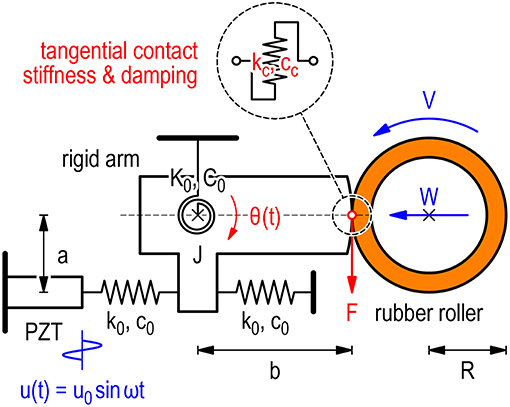
Figure 1. Investigated system: scheme of the measuring system for dynamic response of rubber in sliding contact.
Equation of Motion
The equation of motion of the rigid arm is written as
where (·) is the time derivative and F is the tangential force acting on the rigid arm due to the rubber roller. By using the following notations
the equation of motion can be rewritten as
Note that the phase shift φ0 is coming from the viscoelastic properties of the two translational springs (i.e., k0 and c0), not from the viscoelastic properties of the contact.
Limiting Cases
Case I: No Contact
First, let us consider the situation of “no contact” (i.e., W = 0 and V = 0). Since the rubber roller does not contact with the rigid surface, the tangential force vanishes (i.e., F = 0). Then we obtain the steady-state response Equation (2) with α and φ
respectively, where the dimensionless excitation frequency Ω and the dimensionless damping ratio ζ are given by
respectively.
Case II: Static Contact
Secondly, let us consider the situation of “stationary contact” (i.e., W > 0 and V = 0). With no slippage at the contact, the tangential force is given by
where kc and cc are the tangential contact stiffness and the tangential contact damping, respectively. Then we obtain the angular amplitude and the phase shift in the same forms as Equations (9), (10), where Ω and ζ are given by
respectively.
Case III: Fully Slipping Contact
Thirdly, let us consider the situation of “fully slipping contact” (i.e., W > 0 and V > 0). With considering the frictional force with the constant friction coefficient μ, the tangential force at the contact is given by
This merely shifts the equilibrium position of the oscillator, but does not influence its frequency and damping (Nakano, 2006). Thus, both remain the same as the case of “no contact” and are given by Equations (11, 12).
Arbitrary Case
To examine the arbitrary motion of the system, the equation of motion Equation (8) can be easily solved numerically using the Euler time integration procedure. Therein, the calculation scheme for the contact force is the following: In each time step of the dynamic simulation, it is first assumed that the immediate contact between the contact spring and the oscillator is sticking. Thus, the change of the tangential contact force is equal to
This is valid as long as the absolute value of the tangential force remains smaller than the normal force multiplied with the coefficient of friction. If this condition is violated in the given time step, then the tangential force is set to the normal force times the coefficient of friction with the appropriate sign:
The above equations describe unambiguously the procedure for determining the tangential force in each time step. We will now turn to a qualitative discussion of the simulation results. Thereafter, the simulation results will be compared to some experimental data.
Transition Between Sticking and Slipping Regimes
In the previous section, we identified essentially two limiting cases for the motion of the system. For one of them, the velocity of the roller V is zero (Case II: static contact), while for the other, it is very high (Case III: fully slipping contact). It is clear that when the roller starts rotating, there will be some transition between the two regimes. Some features of this transition are relatively simple and robust, which can be discussed on the qualitative level. We will now illustrate these qualitative features with the numerical results.
Consider first the dependency of the velocity amplitude of the rigid arm on the excitation frequency. This is shown in Figure 2 for both the case of static contact with no slip (right resonance curve, displayed with a blue broken line) and the case of sliding contact with no stick (upper left resonance curve, displayed with a red broken line). If the peripheral velocity of the roller is larger than the velocity amplitude of the rigid arm, then the roller will continuously slide on the rigid arm surface with a relative velocity, which keeps changing its absolute value but not the sign. Therefore, the force of friction will remain constant at any time. This will introduce some static displacement but will not affect the resonance curve. Thus, if the rotation velocity of the roller is larger than the maximum velocity amplitude, the roller does not influence the oscillations and they occur exactly as in the non-contact mode. This is similar to the effects which are seen in the active control of friction by oscillations, where there is also a critical velocity, after which there is no influence of oscillations by the force of friction (Popov, 2016).
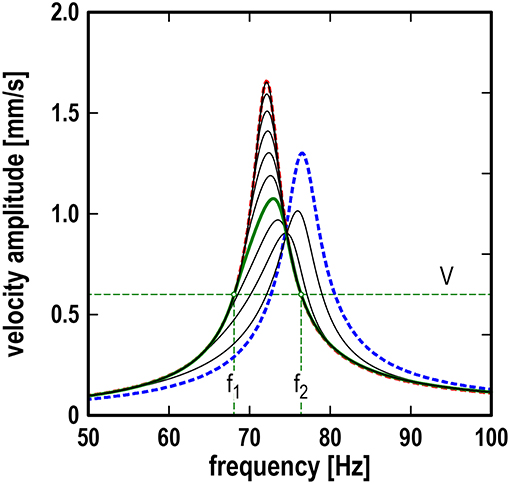
Figure 2. Dependencies of velocity amplitude of rigid arm on excitation frequency for different rubber roller velocities; blue broken line: case II (static contact); red broken line: case III (fully slipping contact). Decrease of sliding velocity (starting from the complete sliding – left high peak) leads first to a decrease of the resonant peak (with practically unchanged resonant frequency) followed by a relatively quick shift of the frequency toward the value corresponding to the stationary contact. For each particular sliding velocity V the curve under the horizontal line at the level of sliding velocity (between frequencies f 1 and f 2) remains unchanged compared to the case of complete sliding.
Let us now consider the case when the roller velocity is smaller than the maximum oscillation velocity. Consider some particular roller velocity, as shown for instance with the horizontal green broken line in Figure 2 and denoted by V. This line has two intersection points with the resonance curve for the velocity amplitude at the frequencies f 1 and f 2. For all frequencies smaller than f 1 or larger than f 2 the roller velocity is larger than the velocity amplitude. This means that in these two regions, the contact with the roller does not influence the resonance curve. Between f 1 and f 2, partial stick occurs, and the resonance curve differs from that without the contact. For the chosen roller velocity, the corresponding dependency is shown with the green bold curve.
Accordingly, we can identify three stages during the decrease of the roller velocity: (1) At very high sliding velocities, the contact with the roller does not influence the resonance curve. (2) When the roller velocity touches the maximum of the resonance curve, first only the top of the curve becomes “cut”—without significantly changing the resonance frequency. (3) Further decrease of the roller velocity leads to a shift of the maximum of the resonance curve to the right; finally, it tends toward the case of static contact.
Note that in Figure 2, the shape of the resonance curve below the level of the roller velocity V remains unchanged compared with the limiting case III (fully slipping contact). Therefore, the resonance curve below the roller velocity level does not depend on the friction coefficient, which only determines the static shift of the oscillator. Between the frequencies f 1 and f 2, the shape of the resonance curve is changed, and it could depend on the friction coefficient. However, most surprisingly, the results of the numerical simulation of the investigated model show that there is no such dependence. Figure 3 illustrates this somewhat counter-intuitive feature. In addition to the resonance curves for the two limiting cases (broken lines), it shows six additional resonance curves (black solid lines), all obtained for the same exemplary sliding velocity of the roller, which is low enough so as to allow an excitation frequency band in which partial stick occurs. Different finite values for the friction coefficient were used to obtain these six additional resonance curves. Not only do all six curves coincide in the frequency region of continuous sliding, but also in the middle frequency band, in which the resonance curves differ from the continuous sliding case due to the periods of stick.
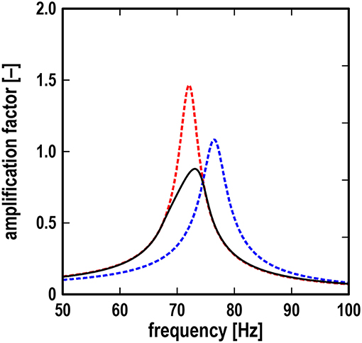
Figure 3. Dependencies of the amplification factor (ratio of rigid arm amplitude to excitation amplitude) on excitation frequency for six different friction coefficients in the range from 0.1 to 1.0; blue broken line: case II (static contact); red broken line: case III (fully slipping contact).
Comparison With Experimental Data
Figure 4 is a photograph of the apparatus developed for measuring dynamic response of rubber in sliding contact, which embodies the model shown in Figure 1. The rubber roller was made of styrene-butadiene rubber with Young's modulus of 15 MPa. As the counter surface of the rubber roller, an abrasive paper with an arithmetic roughness of 4.3 μm was affixed to the curved surface of the rigid arm. The specifications of the system were as follows: the moment of inertia J = 5.0 × 10⁻³ kgm2, the torsional spring constant K0 = 9.9 × 10² Nm, the torsional damping coefficient C0 = 4.3 × 10⁻¹ Nms, the translational spring constant k0 = 1.6 × 10⁴ N/m, the translational damping coefficient c0 = 1.2 × 101 Ns/m, the length a = 30 mm, and the length b = 60 mm. The amplitude and frequency of the PZT actuator were u0 = 2.5 μm, and ω/2π = 50 to 100 Hz, respectively. The normal load was W = 20 N and the peripheral velocity of the rubber roller was V = 20 mm/s. Note that the normal load was applied by pulling a coil spring with a low stiffness to minimize the variation of its value.
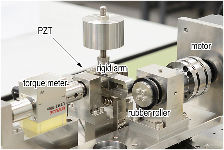
Figure 4. Apparatus developed for measuring dynamic response of rubber in sliding contact.
Let us now compare the analytical and numerical results with some experimental data on resonance curves. As in the previous sections, we first examine the limiting cases (i.e., case I: no contact, case II: static contact, and case III: fully slipping contact). It is shown in Figure 5 that the theoretical results for cases I and II are in very good agreement with the experimental data for no contact (W = 0 N and V = 0 mm/s) and the static contact (W = 20 N and V = 0 mm/s), respectively, where the contact stiffness and contact damping are kc = 8.9 × 10⁴ N/m and cc = 26 Ns/m, respectively, which were determined by fitting experimental data to the theoretical solution Equation (9) with Equations (14), (15). The above values of kc and cc have been used for all simulations in contact: static contact, intermittent slip and full slip.
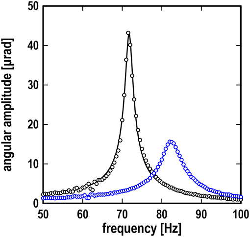
Figure 5. Resonance curves showing frequency response of angular amplitude; black line: theoretical results for case I (no contact) and case III (fully slipping contact); blue line: theoretical result for case II (static contact) at W = 20 N; the blue line is barely visible due to excellent fitting; black symbols: experimental data at W = 0 N and V = 0 mm/s; blue symbols: experimental data at W = 20 N and V = 0 mm/s.
We now turn again to the transition between the limiting cases. From our theoretical results, we expect the resonance amplitude to be lowered and the resonance frequency to be shifted to the right for the case of partial stick, when compared to limiting case I/III (no contact/fully slipping contact). This is confirmed with the experimental data, as can be seen in Figure 6. One can further observe from the graph that the experimental resonance curve differs substantially from the resonance curve for case I/III in a certain frequency range around its resonance frequency, while for higher or lower frequencies the resonance curves still coincide. This is a characteristic feature in the transition phase which was also observed and described in detail in the previous section. On a qualitative level, however, a significant discrepancy of the roller velocities is evident comparing the experimental data of the transition with the corresponding numerical results. In order to obtain a similar resonance frequency and maximum amplitude, the roller velocity in the numerical simulation would have to be smaller by an approximate factor of 0.01 than in the experimental setup. A velocity of V = 20 mm/s as it is shown in Figure 6 would fully comply with the slipping case in the framework of the simplified model. And yet, in the experimental data, we clearly observe a tendency which we would expect only at much lower velocities. At this stage, this leaves an open question which will have to be investigated further in future works. It is expected that a more detailed model for the contact will yield more accurate simulation results and provide insight on why the simplified model chosen in this work leads to the discrepancies in the transition curve.
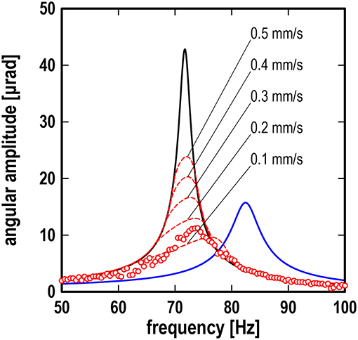
Figure 6. Resonance curves showing frequency response of angular amplitude; black line: theoretical results for case I (no contact) or case III (fully slipping contact); blue line: theoretical result for case II (static contact) at W = 20 N; red lines: numerical results for arbitrary case at W = 20 N and V = 0.1 to 0.5 mm/s; red symbols: experimental data at W = 20 N and V = 20 mm/s.
Conclusion
In this work, we analyzed a measuring device whose basic principle lies in measuring excited oscillations of a mechanical system with a sliding contact between a rubber roller and a rigid surface, which is expected to lead to the extraction of material properties of rubber. In order to obtain a first qualitative and quantitative understanding of the device, we introduced a simple model of the system. Therein, the contact between the rubber roller and the rigid oscillator was modeled with one rheological element consisting of a single spring and a single damper. It was shown that many characteristic features of the system show already with such a simplified one-element model.
Essentially two limiting cases of the system were identified: The static contact, where the rotation velocity of the roller is zero, and the case of continuous sliding, where the velocity of the roller is so high as to never allow phases of stick between the rubber roller and the oscillator. It was shown that the latter coincides with the no contact case. The analytical and numerical results for the limiting cases obtained with the simplified model are in very good agreement with the experimental data.
When the roller starts rotation, there is a transition between the limiting cases. This was also confirmed experimentally. Some features of this transition are relatively simple and robust and were discussed on a qualitative level: At very high sliding velocities, the contact with the roller does not influence the resonance curve. When the roller velocity touches the maximum of the resonance curve of the velocity oscillations, first only the upper portion of the curve is slightly altered, without significantly changing the resonance frequency. A further decrease of the roller velocity leads to a shift of the maximum of the resonance curve to the right before finally it tends toward the static contact case.
The qualitative features of the transition between the limiting cases upon decreasing the roller velocity which were obtained with the simplified model could also be observed in the available experimental data of the transition. On a quantitative level, however, a significant discrepancy of the roller velocities became evident when comparing the experimental data of the transition with the corresponding numerical results. In order to obtain a system response similar to the experimental data, the roller velocity in the numerical simulation had to be smaller than in the experiment by an approximate factor of 0.01. This leaves an open question which will have to be investigated further in future works.
It is expected that a more detailed model for the contact will yield more accurate simulation results and provide insight on why the simplified model chosen in this work leads to the discrepancies in the transition of the resonance curves. A first consideration in future works could be the friction law used in the model. As suggested and discussed in detail in Woodhouse et al. (2015), the Coulomb model in its simplest form (Coulomb, 1821), which we adopted in this work, may be too crude for predicting details of friction-driven vibration. More complex friction laws, for example as they are discussed in Barber (2018), may lead to better results. Therein, a critical component may be the dependence of the friction coefficient on the sliding velocity, see Grosch (1963). Another consideration should be the adoption of a more sophisticated contact model. Roller and oscillator of the apparatus are practically two wheels in contact. Such a rolling contact can be modeled more accurately than in the present paper using more than one rheological element with the method of dimensionality reduction, see Popov et al. (2015); Li and Popov (2017).
Author Contributions
KN and VP conceived the study. KN designed the apparatus. YS, KT, and KK conducted experiments. MP, JB, and FF conducted numerical simulations. All authors contributed to writing the manuscript and approved it.
Funding
The authors are grateful for financial support of the Japan Society for the Promotion of Science (VP) and the Deutsche Forschungsgemeinschaft (MP).
Conflict of Interest Statement
The authors declare that the research was conducted in the absence of any commercial or financial relationships that could be construed as a potential conflict of interest.
Acknowledgments
The authors thank Dr. Y. Osawa, Dr. K. Hagiwara, Mr. S. Hatanaka, and Ms. L. Zimmermann for valuable discussions.
References
Amundsen, D. S., Scheibert, J., Thøgersen, K., Trømborg, J., and Malthe-Sørenssen, A. (2012). 1D model of precursors to frictional stick-slip motion allowing for robust comparison with experiments. Tribol. Lett. 45, 377–369. doi: 10.1007/s11249-011-9894-3
Benad, J. (2018). Fast numerical implementation of the MDR transformations. Fact. Univ. Mech. Eng. 16, 127–138. doi: 10.22190/FUME180526023B
Benad, J., Popov, M., Nakano, K., and Popov, V. L. (2018). Stiff and soft active control of friction by vibrations and their energy efficiency. Forschung Ingenieur. 82, 331–339. doi: 10.1007/s10010-018-0281-1
Braun, O. M., Barel, I., and Urbakh, M. (2009). Dynamics of transition from static to kinetic friction. Phys. Rev. Lett. 103:194301. doi: 10.1103/PhysRevLett.103.194301
Grosch, K. (1963). The relation between the friction and visco-elastic properties of rubber. Proc. R. Soc. Lond. A Math. Phys. Sci. 274, 21–39. doi: 10.1098/rspa.1963.0112
Kürschner, S., Popov, V. L., and He,ß, M. (2015). “Contacts with elastomers,” in Method of Dimensionality Reduction in Contact Mechanics and Friction. (Berlin, Heidelberg: Springer Berlin Heidelberg), 99–113. doi: 10.1007/978-3-642-53876-6_7
Li, Q., and Popov, V. L. (2017). Normal line contact of finite length cylinders. Fact. Univ. Series Mech. Eng. 15, 63–71. doi: 10.22190/FUME170222003L
Mao, X., Popov, V. L., Starcevic, J., and Popov, M. (2017). Reduction of friction by normal oscillations. II. In-plane system dynamics. Friction 5, 194–206. doi: 10.1007/s40544-017-0146-x
Nakano, K. (2006). Two dimensionless parameters controlling the occurrence of stick-slip motion in a 1-DOF system with Coulomb friction. Tribol. Lett. 24, 91–98. doi: 10.1007/s11249-006-9107-7
Nakano, K., and Maegawa, S. (2009). Stick-slip in sliding systems with tangential contact compliance. Tribol. Int. 42, 1771–1780. doi: 10.1016/j.triboint.2009.04.039
Popov, M. (2016). Critical velocity of controllability of sliding friction by normal oscillations in viscoelastic contacts. Fact. Univ. Mech. Eng. 14, 335–341. doi: 10.22190/FUME1603335P
Popov, M., Benad, J., Popov, V. L., and Heß, M. (2015). “Acoustic emission in rolling contacts,” in Method of Dimensionality Reduction in Contact Mechanics and Friction (Berlin: Springer), 207–214. doi: 10.1007/978-3-642-53876-6_14
Popov, V. L. (2017). Contact Mechanics and Friction. Berlin: Springer. doi: 10.1007/978-3-662-53081-8
Popov, V. L., and Heß, M. (2015). Method of Dimensionality Reduction in Contact Mechanics and Friction. Berlin: Springer. doi: 10.1007/978-3-642-53876-6
Popov, V. L., Willert, E., and Heß, M. (2018). Method of dimensionality reduction in contact mechanics and friction: a user's handbook III. Viscoelastic contacts. Fact. Univ. Mech. Eng. 16, 99–113. doi: 10.22190/FUME180511013P
Rao, M. (2003). Recent applications of viscoelastic damping for noise control in automobiles and commercial airplanes. J. Sound Vibration 262, 457–474. doi: 10.1016/S0022-460X(03)00106-8
Saccomandi, G., and Ogden, R. (2004). Mechanics and Thermomechanics of Rubberlike Solids. Wien: Springer. doi: 10.1007/978-3-7091-2540-3
Keywords: rubber, contact, sliding friction, viscoelasticity, contact stiffness, contact damping
Citation: Nakano K, Kawaguchi K, Takeshima K, Shiraishi Y, Forsbach F, Benad J, Popov M and Popov VL (2019) Investigation on Dynamic Response of Rubber in Frictional Contact. Front. Mech. Eng. 5:9. doi: 10.3389/fmech.2019.00009
Received: 21 December 2018; Accepted: 04 March 2019;
Published: 26 March 2019.
Edited by:
Irina Georgievna Goryacheva, Institute for Problems in Mechanics (RAS), RussiaReviewed by:
Luciano Afferrante, Politecnico di Bari, ItalyErik Kuhn, Hamburg University of Applied Sciences, Germany
Fedor Stepanov, Institute for Problems in Mechanics (RAS), Russia
Copyright © 2019 Nakano, Kawaguchi, Takeshima, Shiraishi, Forsbach, Benad, Popov and Popov. This is an open-access article distributed under the terms of the Creative Commons Attribution License (CC BY). The use, distribution or reproduction in other forums is permitted, provided the original author(s) and the copyright owner(s) are credited and that the original publication in this journal is cited, in accordance with accepted academic practice. No use, distribution or reproduction is permitted which does not comply with these terms.
*Correspondence: Ken Nakano, bmFrYW5vQHludS5hYy5qcA==
Valentin L. Popov, di5wb3BvdkB0dS1iZXJsaW4uZGU=