- 1Faculty of Mechanical Engineering, Technion Israel Institute of Technology, Haifa, Israel
- 2Technion Research and Development Foundation, Israel Institute of Metals, Haifa, Israel
- 3Faculty of Materials Science and Engineering, Technion Israel Institute of Technology, Haifa, Israel
The AlCrFe2Ni2 high entropy alloy exhibits an interesting microstructure, which changes considerably when various thermal treatments are applied. These changes are manifested mostly through the precipitation and dissolution of several BCC and FCC phases. To gain better understanding as to the phase evolution in AlCrFe2Ni2 with respect to the thermal history, the microstructures of four thermal states were investigated using Transmission Electron Microscope (TEM) and high resolution TEM. The thermal states included as-cast, homogenized at 1185°C for 75 min, homogenized and aged at 750°C for 4 h, and homogenized and aged at 930°C for 3 h. Common phases to all of the examined thermal states are Fe-rich FCC phase, ordered Ni-Al -rich BCC phase (B2), and disordered Cr-Fe -rich BCC phase. Following homogenization at 1185°C dissolution of the submicron-sized BCC phase particles in the ordered B2 phase was observed. Aging at 750°C resulted in the precipitation of nano-sized B2 platelets and needle-like particles inside the FCC phase domain, while the re-precipitation of nano-sized Cr-Fe globules occurred in the B2 phase. Aging at 930°C resulted mainly in the formation of submicron sized B2 platelets in the FCC phase domain.
Introduction
The 3d transition metals based high entropy alloys (HEAs) have been the focus of attention since the early stages of this branch of metallurgy. These alloys gained attention due to their balanced combination of desired properties: mechanical behavior (strength, ductility), corrosion resistance and high thermal stability (Zhang et al., 2014; Miracle and Senkov, 2017). The most common family of HEAs in this class is the quinary AlCrCoFeNi HEA with various ratios among the constituting elements (Kao et al., 2009, 2011; Qiao et al., 2011; Dong et al., 2014; Munitz et al., 2016; Niu et al., 2019).
Non-equimolar HEAs in the AlCrCoFeNi alloy family have also been investigated. Reddy et al. (2019) found that severe deformation of AlCoCrFeNi2.1 eutectic high entropy alloy by cryo-rolling and subsequent warm-rolling at 600°C imparts high ductility and strength due to the unique lamellar structure (L12+B2) that is formed. Recently, the search for a more affordable HEA led to the elimination of the expensive Co. One of the emerging Co-free alloys, which holds great promise, is the non-equimolar AlCrFe2Ni2 alloy (Dong et al., 2016). While the number of publications dedicated to the study of the AlCrFe2Ni2 HEA is still quite limited, its microstructure is known to bear remarkable similarities with that of the AlCrCoFeNi alloy, and it shares its microstructural sensitivity to the cooling rate (Dong et al., 2016; Li C. et al., 2020; Li Z. et al., 2020).
Thermodynamically, Fe and Cr tend to concentrate more in a disordered FCC solid solution phase, while Ni and Al are typically concentrated in the ordered BCC arrangement (B2 phase). When the cooling rate is extremely high (such as in additive manufacturing) there is not enough time for the solidification route to go through the formation of an FCC phase, and a spinodal decomposition occurs, partitioning the alloy to Fe- and Cr-rich regions and Al- and Ni- rich regions (Wang et al., 2008; Manzoni et al., 2013; Dong et al., 2016; Munitz et al., 2016; Rogal et al., 2019; Li C. et al., 2020; Li Z. et al., 2020). Both regions possess a BCC crystal structure, with the Cr-Fe- rich phase being a configurationally disordered solid solution, and the Al-Ni- rich phase being an ordered B2 (Manzoni et al., 2013; Rogal et al., 2019; Li C. et al., 2020). Both regions share the same lattice parameter (2.88 Å) and therefore their orientation can be identical, thus forming a large contiguous BCC domain. When the solidification rate is slower, or when different post-production heat treatments are performed, the FCC phase, with a lattice parameter of 3.55 Å becomes favorable and grows at the expense of the Cr- and Fe- rich disordered BCC phase.
Munitz et al. (2016) showed that for the AlCrCoFeNi alloy, the as-cast state contained almost no detectable FCC phase, and its volume fraction increased with treatment temperature in the range of . When heat treated at , the reverse phenomenon was observed and all of the formed FCC particles dissolved back into the BCC matrix. Li Z. et al. (2020) showed that for the AlCrFe2Ni2 alloy, an increased carbon content results in a general increase in the volume fraction of the FCC phase. Aside from determining which phases form during the solidification process and their volumetric ratio, the cooling rate and the carbon content can also affect the morphologies of the formed phases, ranging from needle-like particles, globules and plates to elongated worm-shaped domains.
Adding to the previously described microstructural complexity, chromium based carbides are sometimes observed alongside the occasional CrFe σ phase (Munitz et al., 2016; Rogal et al., 2019).
Experimental Procedure
Alloying Procedure
The complete melting of a mixture of the pure elements (Al, Cr, Fe, and Ni) placed in a zirconia crucible, was achieved via a “Consarc” vacuum induction melting furnace. To avoid oxidation, a two-stage procedure was adopted. The furnace chamber was initially vacuumed to a pressure of 1.33⋅(10–6–10–5) MPa, followed by the injection of a protective argon environment at a slight over-pressure of 0.11 MPa. Casting was performed by manual tilting of the crucible in the furnace into a high-density graphite mold. The obtained product was rod-shaped with approximate dimensions of 20 × 20 × 200 mm3.
Heat Treatments
Heat treatments were performed using an electric fiber-insulated chamber furnace. The temperature inside the furnace was monitored via a W-Re thermocouple. Homogenization treatment was performed at 1185°C for 75 min, and the subsequent aging treatments were performed at 750°C for 4 h, and 930°C for 3 h. The aforementioned heat treatments were terminated by water quenching.
Scanning Electron Microscopy (SEM)
A high resolution TESCAN MIRA3 Field Emission Gun SEM was used to observe the micron-scale microstructure. Specimens were prepared via mechanical polishing with SiC papers (1000 grit) and diamond slurries (down to 3 microns). Following the mechanical preparation stages, the specimens were electropolished at 18V for 3 s using a Struers LectroPol machine and A3 solution.
Transmission Electron Microscopy (TEM)
The preparation of TEM samples was performed using a dual-beam FEI Helios NanoLab G3 focused ion beam (FIB) HR-SEM.
Electron diffractions and TEM images were obtained using an FEI Tecnai G2 T20 200 KeV TEM with a LaB6 electron source and an FEI Supertwin objective lens. This microscope is also equipped with a plate camera and a 1K × 1K Gatan 694 retractable slow scan CCD.
High Resolution TEM Imaging and EDS maps were obtained via an FEI Titan Themis 60–300 kV S/TEM equipped with HAADF and an EDS system for local chemical analysis.
Results and Discussion
As-Cast AlCrFe2Ni2
The as-cast alloy was first investigated using TEM. Four main phases were identified: FCC, ordered BCC (B2), disordered BCC and a hexagonal carbide of the M7C3 type. The carbide is most likely a result of a carbon containing substance found within the furnace, however, the exact source of contamination could not be pinpointed. Overall the alloy contains 0.18 wt% carbon.
Figures 1, 2 provide bright field (BF) micrographs and selected area electron diffraction (SAED) patterns obtained from each phase, respectively. A low magnification HRSEM micrograph is also added in Figure 1C to give an overview of the distribution of phases comprising the microstructure.
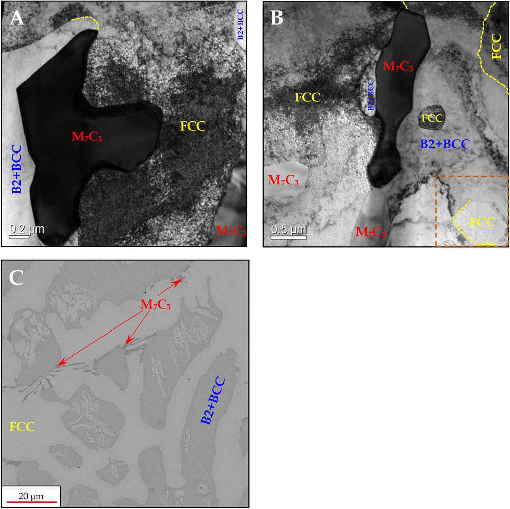
Figure 1. BF-TEM micrographs showing the general morphology of the phases comprising the microstructure in as-cast AlCrFe2Ni2 alloy (A,B). HRSEM micrograph showing the general microstructure in as-cast AlCrFe2Ni2 alloy (C).
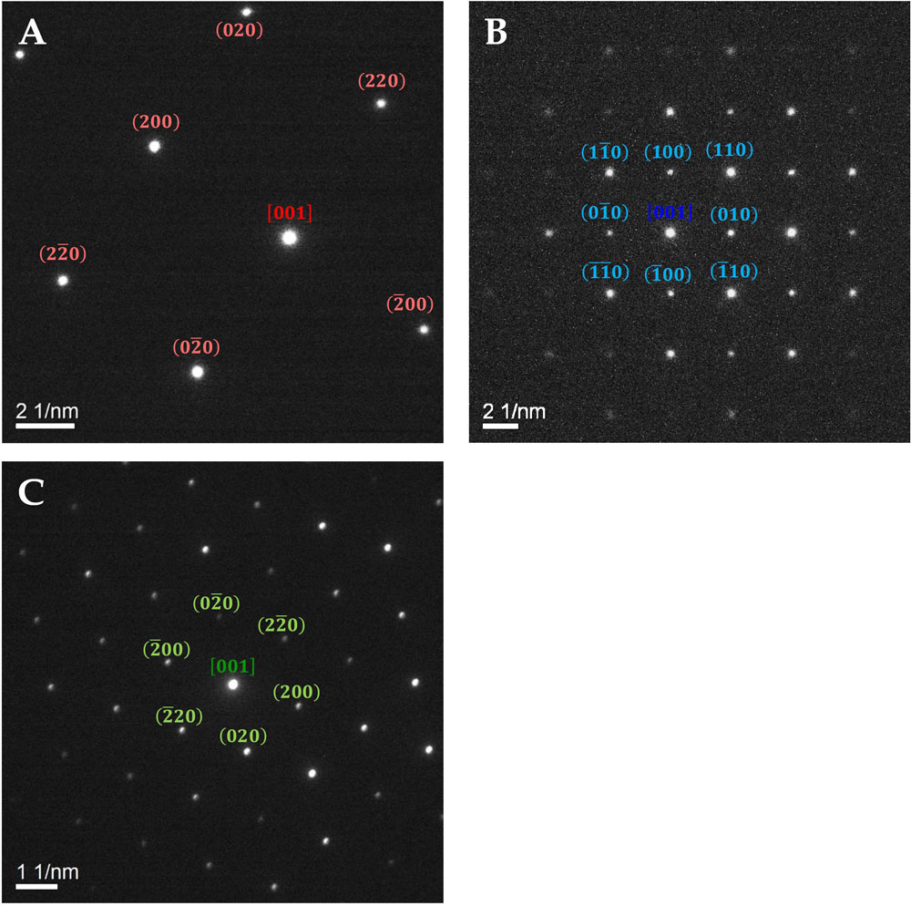
Figure 2. SAED patterns in as-cast AlCrFe2Ni2 alloy – obtained from (A) the FCC phase in zone axis (Z.A.) <001>: (B) the B2 and BCC phases in Z.A. <001>: and (C) the M7C3 phase in Z.A. <001>:.
The ranges of the different phases lattice parameters of, as calculated from the SAED are:
It should be noted that since the BCC globules were extremely small, it was impossible to obtain a separate diffraction pattern from this phase.
Since the B2 and BCC phases shared the same orientation, and their diffraction patterns were indistinguishable from each other due to the very small size of the BCC phase, a high-resolution STEM analysis was performed. Figure 3 shows the BCC particles in the B2 phase in increasing magnifications. Additionally, the FCC-B2 interface was also investigated revealing a dominant Kurdjumov-Sachs orientation relationship.
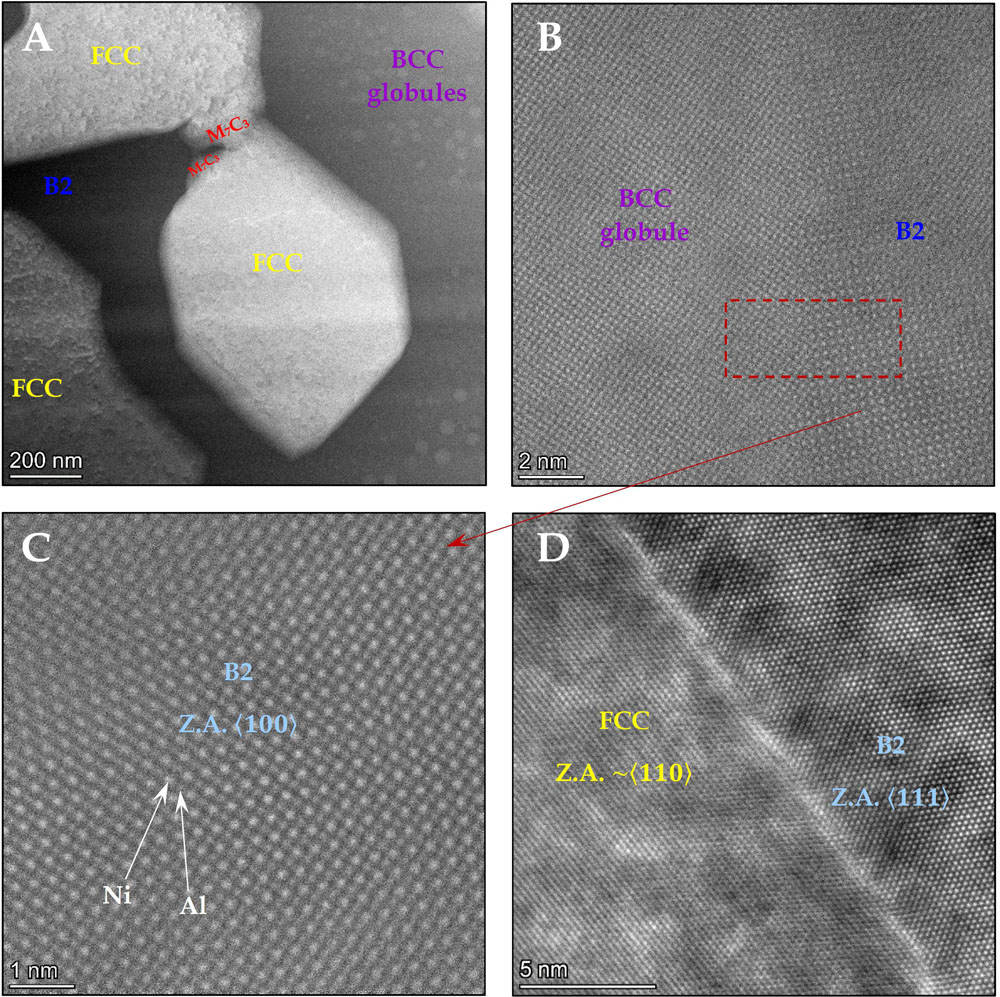
Figure 3. (A) STEM image taken from the dashed square region in Figure 1B showing the brighter globules compared with the darker B2 background; (B) HAADF showing a lattice image in the > 100 >: zone axis of the BCC and B2 domain, and the characteristic order-disorder transition through the interface between the B2 phase and the BCC globules; (C) HAADF of the B2 parent phase in the <001>: zone axis showing the ordering of Ni and Al atoms in the lattice; (D) HAADF image showing the interface between an FCC particle and the B2 phase – demonstrating the near perfect Kurdjumov-Sachs orientation relationship.
A high-resolution EDS map was obtained from the area captured in Figure 3A, in order to better understand the elemental distribution in each of the participating phases in the microstructure.
The HR-EDS analysis presented in Figure 4 suggests that there is a ∼50 nm long precipitate-free zone in the B2 parent phase bordering the FCC particle. Outside of the precipitate-free zone, BCC globules form, ranging in size from a few nanometers to 20–30 nm. Additionally, the M7C3 phase is almost devoid of Ni, and its metallic component is primarily Cr, with some Fe.

Figure 4. High Resolution S/TEM EDS map (STEM mode) of the area captured in Figure 3A in the as-cast AlCrFe2Ni2 alloy.
As evident from Figure 3B, even though both the BCC and B2 phases share the same orientation, there is a clear order-to-disorder transition going from the B2 parent phase to the BCC particles.
The morphology of the globules, and the fact that both the B2 parent phase and the BCC globules embedded in it share the same orientation, suggests that a spinodal decomposition took place. In order to establish the nature of the elemental separation taking place here, a high resolution EDS map of the interface between a BCC globule and the B2 parent phase (taken from the dashed square in Figure 3B) was performed (Figure 5):

Figure 5. High Resolution S/TEM EDS map (STEM mode) of the B2-BCC interface in as-cast AlCrFe2Ni2 alloy.
The maps clearly show that during the spinodal decomposition process Cr and Fe concentrate in the disordered BCC globules, while Ni and Al concentrate more in the ordered B2 phase. The fact that elemental Cr and Fe, and AlNi0.5Fe0.5 all have a BCC crystal structure with the same lattice parameter of 2.87–2.89 Å enables this separation to take place coherently, while preserving the shared orientation of both phases (Hermann, 2011; Kotov et al., 1972).
The globular morphology and increased Cr-Fe content of the BCC globules, together with their shared orientation with the B2 matrix they are embedded in, was also found in publications dealing with similar Co-containing HEAs such as AlCo0.5Cr0.5FeNi (Chaudhary et al., 2018) and Al0.7CoCrFeNi (Gwalani et al., 2019), especially after aging at relatively low temperatures (∼600°C).
Finally, in order to complete the analysis of the as-cast product, a high-resolution EDS point analysis was performed. The results are presented in Table 1.
Homogenized AlCrFe2Ni2
The microstructural investigation of the homogenized AlCrFe2Ni2 revealed the following phases: FCC, ordered BCC (B2), and a cubic carbide phase of the M23C6 type (FCC). Therefore, the two main microstructural changes that occurred due to the homogenization treatment were the dissolution of the Cr-Fe- rich disordered BCC globules and the transformation of the hexagonal M7C3 carbide into the cubic Cr23C6 carbide. Additional precipitation of B2 platelets/whiskers inside the FCC phase was observed in SEM images, perhaps indicating that for this alloy this treatment is more of an extreme form of aging rather than pure homogenization.
Figures 6, 7 provide BF-TEM micrographs and SAED patterns obtained from each phase in the homogenized alloy, respectively. Figure 6B shows an HRSEM image of the general microstructure:
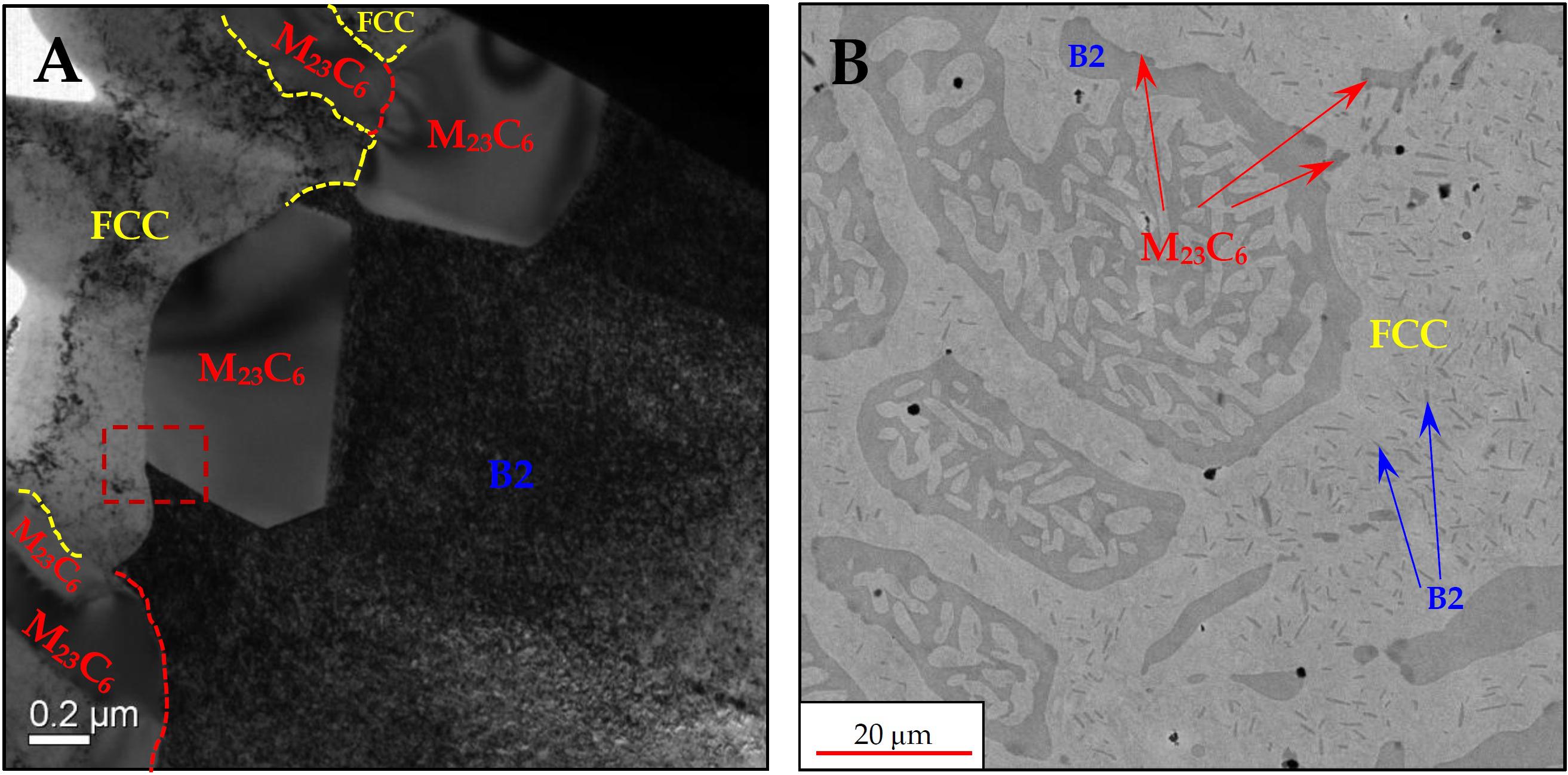
Figure 6. (A) BF-TEM micrographs showing the general morphology of the phases comprising the microstructure in homogenized AlCrFe2Ni2 alloy; (B) An HRSEM micrograph showing the general microstructure in homogenized AlCrFe2Ni2 alloy.
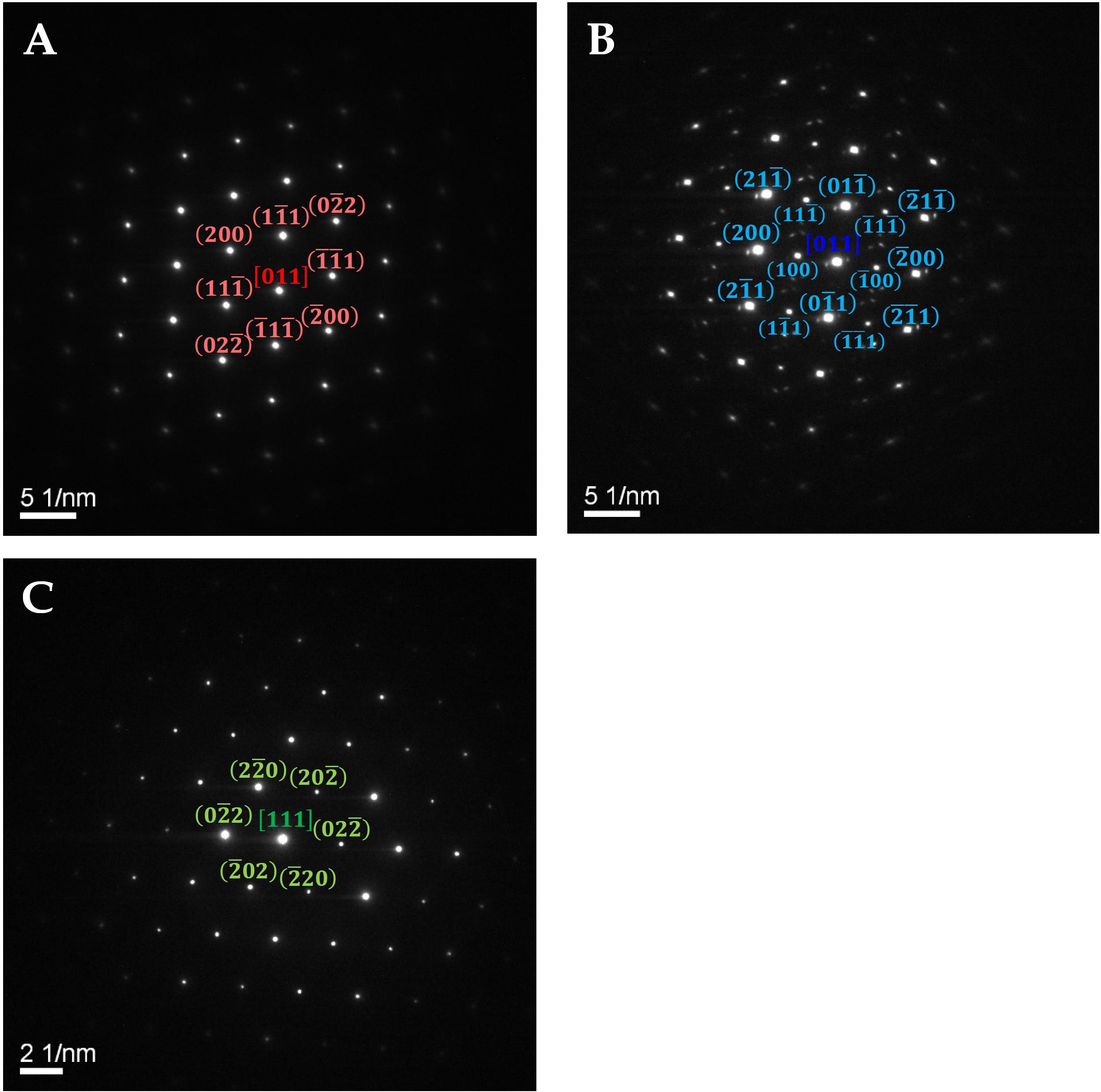
Figure 7. SAED patterns in the homogenized AlCrFe2Ni2 alloy – obtained from (A) the FCC phase in Z.A. > 011 >: (B) the B2 phase in Z.A. > 011 >:; (C) the FCC M23C6 phase in Z.A. > 111 >:.
The lattice parameter of the M23C6 phase was calculated from the SAED to be: a= 10.8 Å, which is slightly higher than the theoretical value for Cr23C6 of a = 10.66 Å (Powder Diffraction, 1985). The difference in lattice parameter could be due to measurement errors associated with the TEM, or the deviation from the perfect stoichiometry due to incorporation of Fe atoms or increased C content.
High resolution EDS mapping of the tri-phase junction shown in the dashed square in Figure 6 is presented in Figure 8:
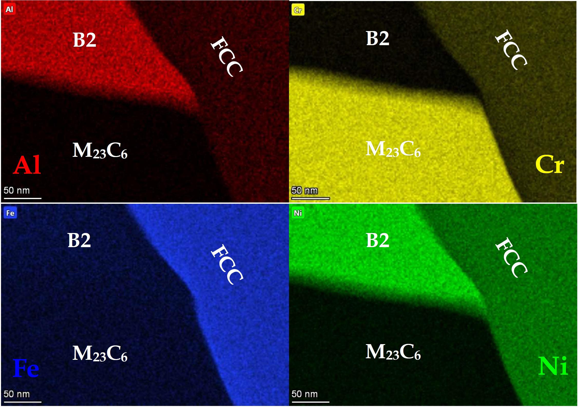
Figure 8. High Resolution S/TEM EDS map (STEM mode) of the area marked in Figure 6 in the homogenized AlCrFe2Ni2 alloy.
The elemental separation among the three phases, is very similar to the as-cast alloy, including the carbide phase.
A high-resolution EDS point analysis was performed in the homogenized alloy as well. The results are presented in Table 2.
The transformation of the carbide may seem surprising, since the M7C3 carbide is more stable than the M23C6, and in a binary Cr-C system, heating Cr23C6 carbide will result in the formation of Cr7C3, and not the other way around. The reverse trend we observed is rationalized for the AlCrFe2Ni2 alloy using the fact that as the temperature rises, more carbon can be dissolved in the surrounding B2 and FCC phases, which leaves the carbide phase with a lower carbon-to-metal ratio, resulting in the M7C3-to-M23C6 transformation.
A look at the lattice images of both carbides, viewed from their threefold symmetry zone axes, shows their similarity (Figure 9).
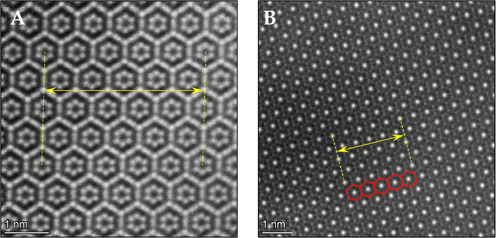
Figure 9. (A) HAADF showing a lattice image in Z.A. <001>: of the hexagonal M7C3; (B) HAADF showing a lattice image in Z.A. > 111 >: of the cubic M23C6.
Noteworthy is that the loss of carbon is also accompanied by a reduction in the corresponding d-space defined by the periodic hexagonal structure.
Homogenized and Aged (750°C) AlCrFe2Ni2
Post-homogenization aging treatment at 750°C for 4 h resulted in the re-precipitation of nano-globular BCC particles within the B2 phase domain. Additional precipitation occurred inside the FCC phase, in the form of nano sized B2 platelets. The M23C6 carbide remained unchanged.
Figure 10 presents BF-TEM micrographs and an HRSEM micrograph, depicting the general microstructure obtained following homogenization at 1185°C for 75 min and subsequent aging at 750°C for 4 h.
Figure 10. (A–C) BF-TEM micrographs showing the general morphology of the phases and precipitates comprising the microstructure in homogenized and aged (750°C) AlCrFe2Ni2 alloy; (D) HRSEM micrograph showing the general microstructure in aged (750°C) AlCrFe2Ni2 alloy.
As shown in Figure 10, the characteristic thickness of the platelets is 20–50 nm, while their length ranges from 100 to 300 nm. The BCC globules inside the B2 phase were observed to be quite uniform in size – approximately 30–50 nm.
The SAED pattern obtained from each phase are given in Figure 11. A clear SAED of the BCC globules could not be obtained due to their small dimensions.
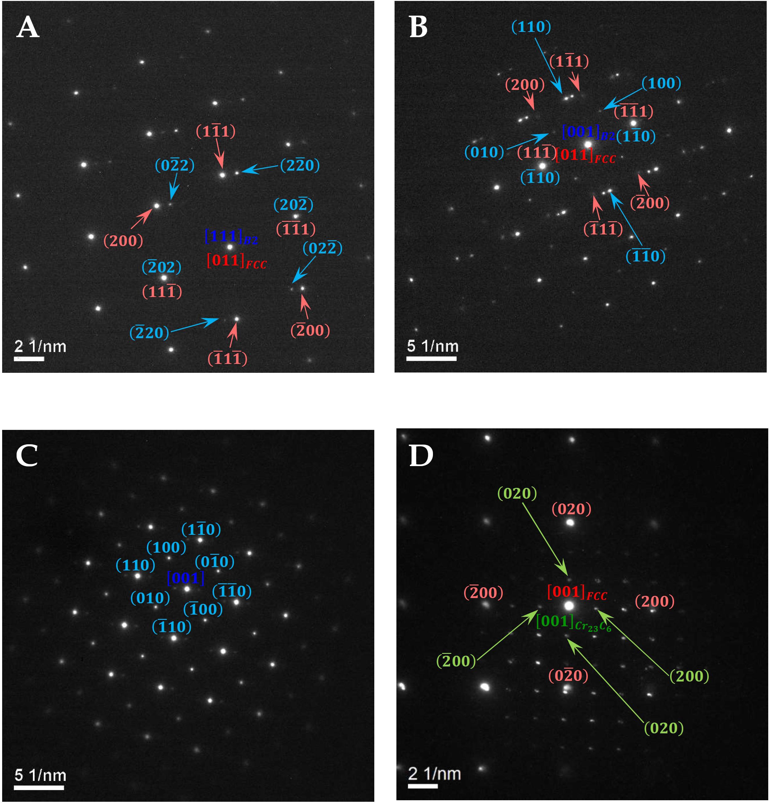
Figure 11. SAED diffraction patterns in the homogenized and aged (750°C) AlCrFe2Ni2 alloy – obtained from (A) a B2 platelet in Z.A. > 111 >: inside the FCC phase in Z.A. > 110 >:; (B) a B2 platelet in Z.A. > 100 >: inside the FCC phase in Z.A. > 110 >:; (C) the B2+BCC phase domain in Z.A. > 100 >:; (D) a M23C6 particle bordering the FCC phase.
Figure 11 clearly shows that each B2 precipitate can possess a different orientation relative to that of the FCC parent phase such as the Kurdjumov-Sachs relationship in Figure 11A or the Nishiyama–Wasserman relationship in Figure 11B. Since the M23C6 carbide also possesses an FCC structure, it was no surprise that some crystals showed almost identical orientation to that of the neighboring FCC parent phase (Figure 11D). The diffraction pattern in Figure 11D also exhibits the 1:3 ratio of the lattice parameters of both phases.
HR-TEM images and lattice images were also obtained in order to further investigate the BCC nano-globules and the B2 nano-precipitates in the FCC phase.
The nature of the ordered B2 platelets and the order-to-disorder transition in the B2-BCC globules’ interface are only evident in HRTEM analyses as shown in Figure 12.
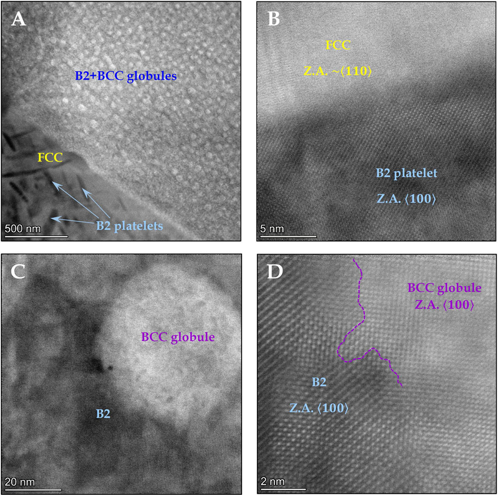
Figure 12. (A) STEM image showing the extremely fine precipitates in the B2 and FCC phases characteristic of the microstructure of the homogenized and aged (750°C) AlCrFe2Ni2 alloy. (B) HAADF of a B2 platelet showing a lattice image in the > 100 >: zone axis, relative to the FCC parent phase whose zone axis is close to > 110 >:; (C) Low magnification HAADF of the B2+BCC domain in the > 100 >: zone axis, showing the outlines of a globule; (D) HAADF image showing the interface between the ordered B2 parent phase and the BCC globule.
Comparing the obtained microstructure in this research, with similar alloys having undergone aging treatment (Chaudhary et al., 2018; Gwalani et al., 2019), It appears that the slightly higher aging temperature here resulted in the precipitation of B2 precipitates inside the FCC parent phase instead of L12.
Homogenized and Aged (930°C) AlCrFe2Ni2
Post-homogenization aging at 930°C for 3 h resulted in the dissolution of the majority of the BCC nano-globules in the B2 parent phase. Few globules were able to grow large enough (around 100 nm) without dissolving. The B2 nano-platelets have also grown considerably due to aging at a higher temperature (200–500 μm in length and width; less than 100 μm in thickness), but were much more ubiquitous than the BCC globules. Most likely, the interfacial incoherence and crystallographic mismatch between the platelets and the FCC parent phase, require higher temperatures to initiate dissolution than in the case of the coherent BCC globules. The M23C6 carbide remained unchanged.
Figure 13 presents bright field TEM micrographs and an HRSEM image, depicting the general microstructure obtained following homogenization at 1185°C for 75 min and aging at 930°C for 3 h. The corresponding SAED pa[3-8]tterns are shown in Figure 14.
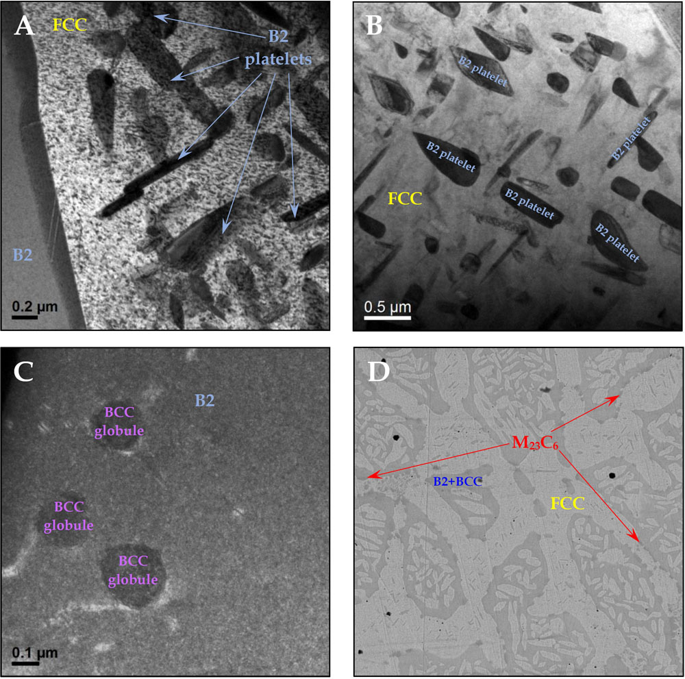
Figure 13. (A–C) BF-TEM micrographs showing the general morphology of the phases and precipitates comprising the microstructure of the homogenized and aged (930°C) AlCrFe2Ni2 alloy; (D) HRSEM micrograph showing the general microstructure in aged (930°C) AlCrFe2Ni2 alloy.
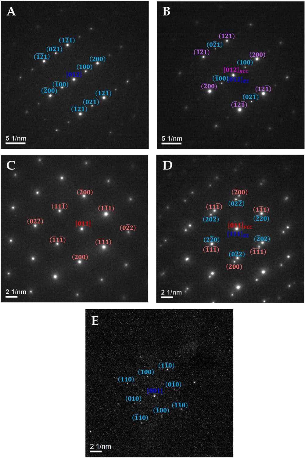
Figure 14. SAED patterns in the homogenized and aged (930°C) AlCrFe2Ni2 alloy – obtained from (A) the B2 parent phase in Z.A. > 210 >:; (B) a BCC globule in Z.A. > 210 >: inside the B2 phase; (C) the FCC parent phase in Z.A. > 110 >:; (D) a B2 platelet in Z.A. > 111 >: inside the FCC parent phase in Z.A. > 110 >: exemplifying the Kurdjumov-Sachs orientation relationship; (E) a B2 platelet in Z.A. <001>: inside the FCC parent phase.
Since many of the platelets and BCC globules are still very thin, the background of their respective parent phases is still visible in the diffraction patterns.
Summary of Microstructural Changes
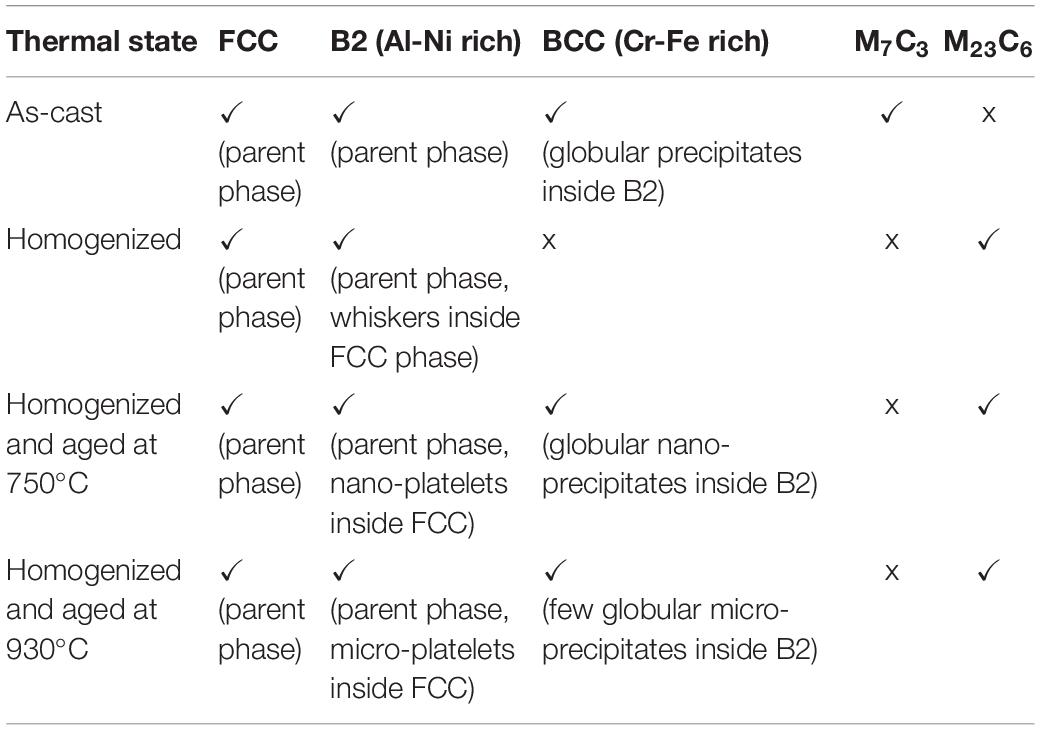
The following table summarizes the main microstructural features present in each thermal state of the AlCrFe2Ni2 alloy:
Microhardness Tests
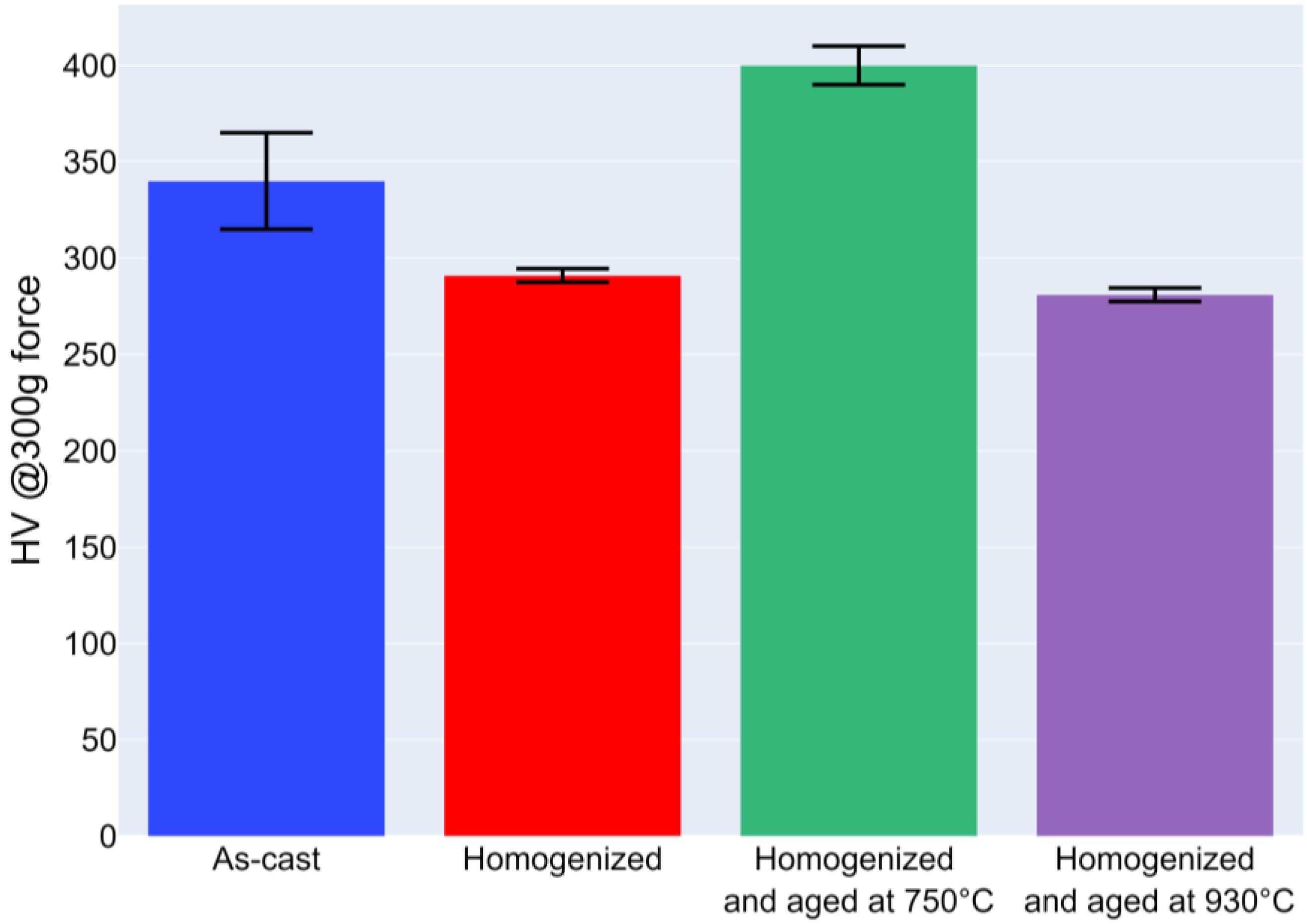
To get a preliminary indication of the expected effect of the investigated four thermal states on the mechanical properties, Vickers microhardness tests were conducted (Figure 15). For the as-cast state, the Vickers hardness was measured to be 340 ± 25, which is roughly 10% higher than the value reported in Li C. et al. (2020), for a similar alloy (albeit without the 1%a carbon presence). Upon homogenization, which resulted in some grain growth and carbide transformation, the hardness decreased to 291 ± 3.5. For the two aging treatments considered in this work, considerable hardening (with respect to the homogenized state) was observed for the 750°C aged state (400 ± 10), while aging at 930°C led to a slight decrease in hardness (281 ± 3.5). The difference in measured hardness between the two aged state agrees with the observed microstructures summarized in Table 3. Under the 930°C aging treatments, both the B2 platelets (inside FCC) and BCC precipitates (inside B2) were observed to be larger in size, while the BCC precipitates appeared to be rather sparse, suggesting that 3 h at 930°C lead to over-aging.
Summary
The microstructure of the AlCrFe2Ni2 high entropy alloy was studied under four thermal conditions, namely: As-cast; Homogenized (75 min at 1185°C); Homogenized and aged (240 min at 750°C) and homogenized and aged (180 min at 930°C). The as cast alloy was found to comprise three metallic phases and a carbide phase: FCC; B2; BCC globules embedded in the B2 matrix and a hexagonal M7C3 carbide, where Cr is the dominant metal. Upon being subjected to the homogenization treatment, the Cr-Fe-rich BCC globules were observed to dissolve, while the M7C3 phase has transformed into a cubic Cr23C6 phase. The carbide transformation was accompanied by an increase in the Fe-to-Cr atomic ratio in the carbide and a lower carbon-to-metal ratio, the latter, most likely, resulting from the increased dissolution of C in the neighboring FCC and B2 parent phases, due to the higher temperature. Subsequent Aging treatments resulted in re-precipitation of the BCC particles within the parent B2 phase, accompanied by the precipitation of nano sized B2 platelets in the parent FCC phase. With increasing aging temperature, the size of both BCC and B2 precipitates was found to increase. A striking difference between the two aging treatments was found in the distribution and size of the two precipitating phases. Aging at 750°C, resulted in smaller, more ubiquitous BCC globules, when compared with the larger, less frequent BCC particles observed in the alloy aged at 930°C. The B2 nano-platelets, embedded in the FCC phase, were observed to grow larger with increasing aging temperature, however their distribution in the parent phase was not observed to vary much between the two studied aging treatments.
Data Availability Statement
All datasets presented in this study are included in the article/supplementary material.
Author Contributions
SA and EE: TEM work. EE: TEM diffractions analysis. EE, SO, and MB: writing the revised manuscript. All authors contributed to the article and approved the submitted version.
Funding
This research was supported by the Ministry of Science, Technology and Space, the State of Israel in the frame of the M-era. Net Joint Call 2017, Project NADEA (No. 5129).
Conflict of Interest
EE was employed by the company Technion Research and Development Foundation Ltd.
The remaining authors declare that the research was conducted in the absence of any commercial or financial relationships that could be construed as a potential conflict of interest.
References
Chaudhary, V., Gwalani, B., Soni, V., Ramanujan, R. V., and Banerjee, R. (2018). Infuence of Cr substitution and temperature on hierarchical phase decomposition in the AlCoFeNi high entropy alloy. Sci. Rep. 8:15578.
Dong, Y., Gao, X., Lu, Y., Wang, T., and Lu, Y. (2016). A multi-component AlCrFe2Ni2 alloy with excellent mechanical properties. Mater. Lett. 169, 62–64. doi: 10.1016/j.matlet.2016.01.096
Dong, Y., Zhou, K., Lu, Y., Gao, X., Wang, T., and Lu, Y. (2014). Effect of vanadium addition on the microstructure and properties of AlCoCrFeNi high entropy alloy. Mater. Design 57, 67–72. doi: 10.1016/j.matdes.2013.12.048
Gwalani, B., Gangireddy, S., Zheng, Y., Soni, V., Mishra, R. S., and Banerjee, R. (2019). Infuence of Ordered L12 precipitation on strain-rate dependent mechanical behavior in a eutectic high entropy alloy. Sci. Rep. 9, 1–13.
Hermann, K. (2011). Crystallography and Surface Structure: An Introduction for Surface Scientists and Nanoscientists. Weinheim: Wiley-VCH Verlag GmbH & Co, 265–266.
Kao, Y.-F., Chen, S.-K., Chen, T.-S., Chu, P.-C., Yeh, J.-W., and Lin, S.-W. (2011). Electrical, magnetic, and Hall properties of AlxCoCrFeNi high-entropy alloys. J. Alloys Compounds 509, 1607–1614.
Kao, Y.-F., Chen, T.-S., Chen, S.-K., and Yeh, J.-W. (2009). Microstructure and mechanical property of as-cast, -homogenized, and -deformed AlxCoCrFeNi (0≤x≤2) high-entropy alloys. J. Alloys Compounds 488, 57–64. doi: 10.1016/j.jallcom.2009.08.090
Kotov, A. P., Zelenin, L. P., Bronfin, M. B., Sidorenko, F. A., and Gel’d, P. V (1972). Structure and magnetic properties of solid solutions of iron and nickel monoaluminides in each other. Phys. Met. Metall. 33, 142–146.
Li, C., Qu, Y., Zhang, Y., Lv, Q., and Qi, H. (2020). Effect of deep cryogenic treatment on the microstructure and mechanical properties of AlCrFe2Ni2 High-entropy alloy. Mater. Res. Express 7:036504.
Li, Z., You, J. H., Guo, Y., Li, C., Zhang, Y., and Liu, Z. (2020). Phase transition mechanism and mechanical properties of AlCrFe2Ni2 high-entropy alloys with changes in the applied carbon content. Adv. Eng. Mater. 22, 1–7.
Manzoni, A., Daoud, H., Völkl, R., Glatzel, U., and Wanderka, N. (2013). Phase separation in equiatomic AlCoCrFeNi high-entropy alloy. Ultramicroscopy 132, 212–215. doi: 10.1016/j.ultramic.2012.12.015
Miracle, D. B., and Senkov, O. N. (2017). A critical review of high entropy alloys and related concepts. Acta Materialia 122, 448–511. doi: 10.1016/j.actamat.2016.08.081
Munitz, A., Salhov, S., and Frage, S. H. N. (2016). Heat treatment impacts the micro-structure and mechanical properties of AlCoCrFeNi high entropy alloy. J. Alloys Compounds 683, 221–230. doi: 10.1016/j.jallcom.2016.05.034
Niu, P. D., Li, R., Yuan, T. C., Zhu, S. Y., Chen, C., Wang, M. B., et al. (2019). Microstructures and properties of an equimolar AlCoCrFeNi high entropy alloy printed by selective laser melting. Intermetallics 104, 24–32. doi: 10.1016/j.intermet.2018.10.018
Powder Diffraction (1985). 00-035-0783, in Powder Diffraction 1985. Newtown Square, PA: International Centre for Diffraction Data.
Qiao, J. W., Ma, S. G., Huang, E. W., Chuang, C. P., Liaw, P., and Zhang, Y. (2011). Microstructural characteristics and mechanical behaviors of AlCoCrFeNi high-entropy alloys at ambient and cryogenic temperatures. Mater. Sci. Forum 688, 419–425. doi: 10.4028/www.scientific.net/msf.688.41
Reddy, S. R., Yoshida, S., Bhattacharjee, P. P., Sake, N., Lozinko, A., Guo, S., et al. (2019). Nanostructuring with structural-compositional dual heterogeneities enhances strength-ductility synergy in eutectic high entropy alloy. Sci. Rep. 9, 1–9.
Rogal, L., Szklarz, Z., Bobrowski, P., Kalita, D., Garzeł, G., Tarasek, A., et al. (2019). Microstructure and mechanical properties of Al-Co-Cr-Fe-Ni base high entropy alloys obtained using powder metallurgy. Metals Mater. Int. 25, 930–945. doi: 10.1007/s12540-018-00236-5
Wang, Y. P., Li, B. S., Ren, M. X., Yang, C., and Fu, H. Z. (2008). Microstructure and compressive properties of AlCrFeCoNi high entropy alloy. Mater. Sci. Eng. A 491, 154–158.
Keywords: high entropy alloy, transmission electrom microscopy, microstructural evolution in metal, iron-nickel alloy, phase precipitation behavior
Citation: Eshed E, Abd El Majid S, Bamberger M and Osovski S (2020) TEM and High Resolution TEM Investigation of Phase Formation in High Entropy Alloy AlCrFe2Ni2. Front. Mater. 7:284. doi: 10.3389/fmats.2020.00284
Received: 01 June 2020; Accepted: 27 July 2020;
Published: 27 August 2020.
Edited by:
Sheng Guo, Chalmers University of Technology, SwedenReviewed by:
Zhiqiang Fu, South China University of Technology, ChinaBharat Gwalani, Pacific Northwest National Laboratory (DOE), United States
Copyright © 2020 Eshed, Abd El Majid, Bamberger and Osovski. This is an open-access article distributed under the terms of the Creative Commons Attribution License (CC BY). The use, distribution or reproduction in other forums is permitted, provided the original author(s) and the copyright owner(s) are credited and that the original publication in this journal is cited, in accordance with accepted academic practice. No use, distribution or reproduction is permitted which does not comply with these terms.
*Correspondence: Eyal Eshed, ZXlhbGVAdHJkZi50ZWNobmlvbi5hYy5pbA==
 Eyal Eshed
 Suzan Abd El Majid3
 Shmuel Osovski

