 Hui Xu
 Renke Kang1
- 1Key Laboratory for Precision and Non-traditional Machining Technology of Ministry of Education, Dalian University of Technology, Dalian, China
- 2School of Mechanical Engineering and Automation, University of Science and Technology, Liaoning, Anshan, China
- 3Shaft Center, Xi’an Aero-Engine Plc, Xi’an, China
Removing carbon deposition (CD) has always been a challenging problem. On the inner surface of a turbo shaft, CD is observed by scanning electron microscopy (SEM) to analyze its microstructure and composition, and its formation mechanism is analyzed by X-ray diffraction (XRD), infrared spectroscopy, and Raman spectroscopy. Considering the physical and chemical properties of deposited carbon, chemically assisted magnetic grinding (CAMG) is proposed and tested by a translational permanent magnet grinding device. By analyzing the removing mechanism of CAMG, response surface analysis is adopted to analyze the influence law of surface roughness based on the interactions between pairs of the three following parameters: the rotational speed of the rotating magnetic field, needle type, and grinding time. The optimal process parameters can be obtained with a rotational speed of the rotating magnetic field of 600 r/min, a needle type of Φ 1.0 × 5 mm, and a grinding time of 60 min. The surface quality of the workpiece processed by CAMG can be comprehensively appraised by observing the microstructure, calculating the carbon deposit removal ratio and testing the surface stress. Compared to single magnetic grinding, CAMG is more environmentally friendly and has a higher removal ratio and better surface quality with an obvious decrease in residual stress. By professional tests, the remaining deposited carbon is less than the specified value required by the technology, which satisfies the requirements of enterprises.
Introduction
A turbo shaft is the main driving part of an aeroengine. Since the engine often runs at a temperature greater than 500 degrees, under catalysis of metal, carbon deposition (CD) can be produced on the inner surface of a turbo shaft after a series of oxidation reactions, pyrolysis, cracking, dehydrogenation, coking, and polymerization from the fuel in the engine (Tumuluri et al., 2017). In a real working environment, in a single flight when the temperature exceeds 400 degrees and in multiple flights when the temperature exceeds 300 degrees, CD can be visually observed on the engine fuel system parts (Li et al., 2014). Dr. Robert E. Kauffman (Kauffman et al., 2000) discovered that aero fuel can produce deposited carbon particles at a temperature of 225 degrees after 7 h without antioxidants. When the temperature exceeds 325 degrees, the antioxidants in the aero fuel can be consumed quickly. Carbon deposition can occur more quickly when no antioxidant exists. Carbon deposition in the turbo shaft can impact the dynamic balance of the plane, which substantially influences flight safety. Therefore, when an aeroengine turbo shaft runs more than 300 h, it must be cleaned (Jia, 2005).
Carbon deposition in engines has obtained an increasing amount of attention from aviation industry countries. Although a considerable amount of domestic and international research has addressed the formation mechanism of CD, excellent methods of removing carbon deposits are scarce. Jiang et al. (2017) analyzed the impact and harm of CD in car engines, introduced its formation mechanism, and proposed a high-purity hydrogen removing method and tested its effect. Huang et al. (2011) conducted a characteristics analysis of the coking CD on the surface of a Nickel-base-alloy nozzle of an aeroengine by scanning electron microscopy (SEM), transmission electron microscopy, X-ray diffraction (XRD), and other methods. A graphite-like structure and bonding phenomenon between the alloy metal and carbon in the aeroengine were observed. Liu et al. (2014) analyzed the reason and mechanism of CD on the valve of a gasoline engine and suggested ways to optimize engine design and reduce CD. Wang et al. (2017) proposed the utilization of fused salts to eliminate CD on the valve of an automation engine after analyzing its microstructure and formation mechanism. The removal of deposited carbon has been studied previously. To study the molten salt cleaning process for removing carbon deposited on a remanufacturing engine valve, Yao et al. (2015) applied sodium hydroxide, sodium nitrate, and sodium nitrite as a molten salt system and binary nitrate NaNO3–NaNO2 as a cleaning medium under the alkaline condition of 250–380°C. A quadratic model was simultaneously established to predict the cleaning cycle. After a series of optimization tests, it was concluded that the best cleaning conditions were 30% NaOH, at least 40% NaNO2, a cleaning temperature of 330–360°C, and a maximum cleaning cycle of 5 min. According to the principle of ultrasonic cleaning and related research of the low-vortex axial parts cleaning process via the design of aeroengine large, low-pressure turbine small parts, low-pressure turbine shaft parts, and low-vortex axial parts cleaning process simulation test, Hao (2016) determined the ultrasonic cleaning technology of these parts based on the design for large-scale ultrasonic cleaning equipment, which is used for aviation engine low vortex axial parts cleaning problems.
Currently, carbon deposited on the inner surface of an aeroengine is mainly eliminated by disassembling parts, manual scrubbing parts, degreasing parts with hot water, rinsing parts with warm water, and soaking parts with alkali solution. The entire period is so long that the parts’ surfaces may become scratched and damaged, which causes poor effects and low efficiency. Additionally, the workers’ labor intensity is very high, and the working environment is full of poisonous and harmful gases. Since the engine is often running at high temperature and high pressure, the deposited carbon has been graphitized and even absorbs some metal atoms. In some military plane aeroengines, where the temperature exceeds 1,600 degrees, permeation and dissociation of the stubborn carbon adhered to the alloy surface by alkali solution is difficult. Therefore, the traditional cleaning process cannot have a better effect or satisfy the service demand.
For these problems of the removing technology, chemically assisted magnetic grinding (CAMG) is proposed to remove the carbon deposited on the inner surface of an aeroengine turbo shaft to enable the process to satisfy the cleaning requirements.
Formation Mechanism of CD
Analysis of the Microstructure of CD
A titanium–alloy aeroengine turbo shaft, which was dissembled and provided by an enterprise, is selected in this experiment. In the environment of high temperature and high pressure, a large amount of deposited carbon gathers on the inner surface of the turbo shaft. Figure 1A shows the microstructure of the workpiece. It is observed that there are many cracks on the surface of the CD, which is mainly composed of black blocks and flakes. As shown in Figure 1B, irregularity is observed on the surface of the CD, and white, shiny solid particles of different shapes and sizes are distributed unevenly in the cracks between the blocks. As shown in Figures 1C,D, the particles are accumulated and embedded in a disorderly manner. In the formation of a CD, disorderly cracks and pits appear, which will increase the possibility of a new CD. Thus, the CD will consist of coke and will deteriorate gradually.
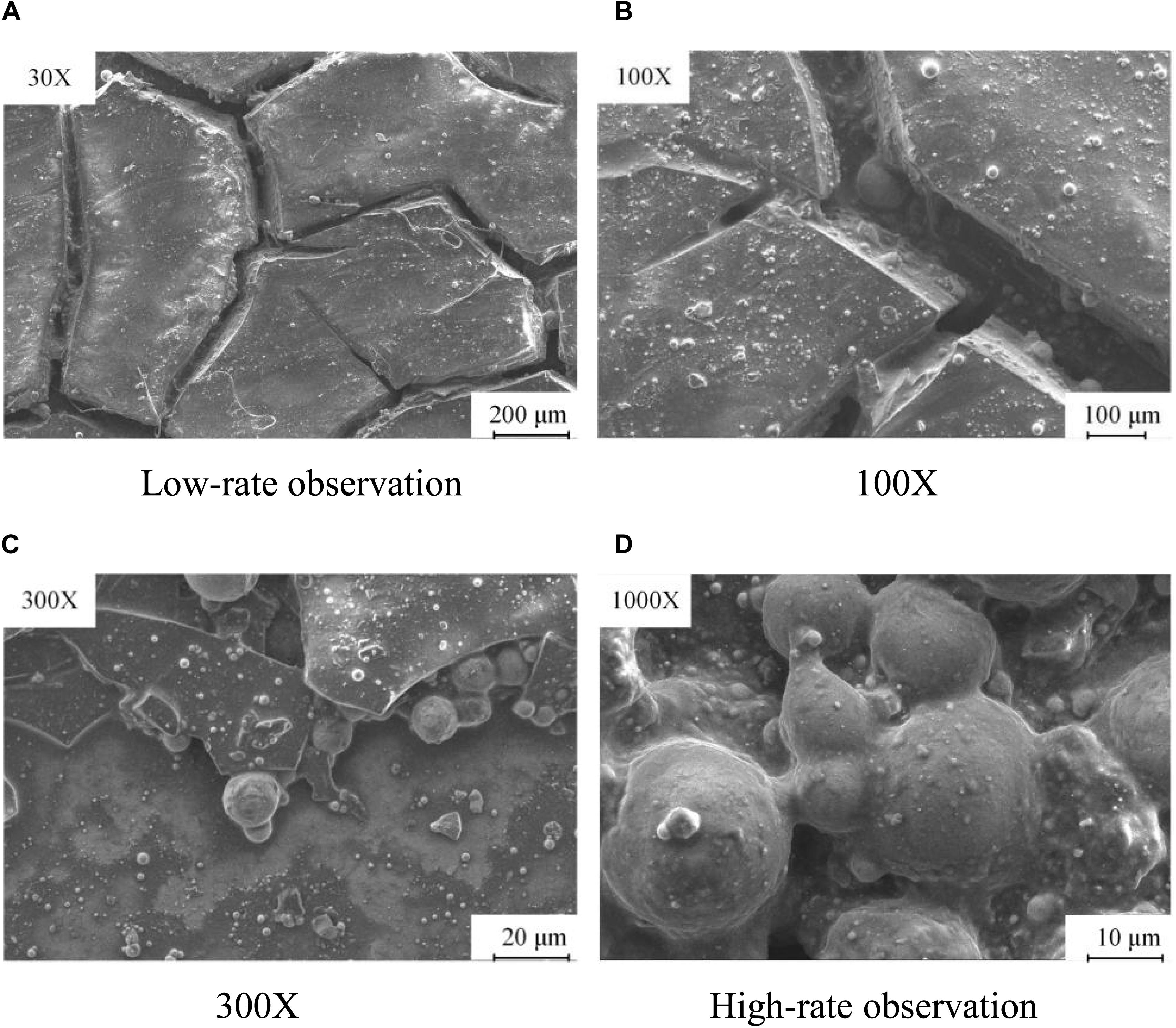
Figure 1. Diagram of the microstructure of a carbon deposit. (A) Low-rate observation. (B) 100×. (C) 300×. (D) High-rate observation.
Composition of Carbon Deposits
As shown in Figure 2, in a carbon deposit, there are many elements, such as carbon, oxygen, silica, aluminum, titanium, iron, and manganese, among which carbon has the highest mass percentage and atomic percentage of 53.2 and 72.1%, respectively, and oxygen has the second highest mass percentage and atomic percentage of 18.6 and 19.3%, respectively. Metal elements, such as Ti, Fe, Al, and Mn, from the base material of the turbo shaft, account for a small proportion of the total mass. In the high-temperature and high-pressure environment, carbon is deposited on the inner surface of the turbo shaft, and after a reaction, the deposited carbon gradually permeates into the metal layer, which causes a transfer of metal atoms from the base into the metal (Zhang et al., 2018).
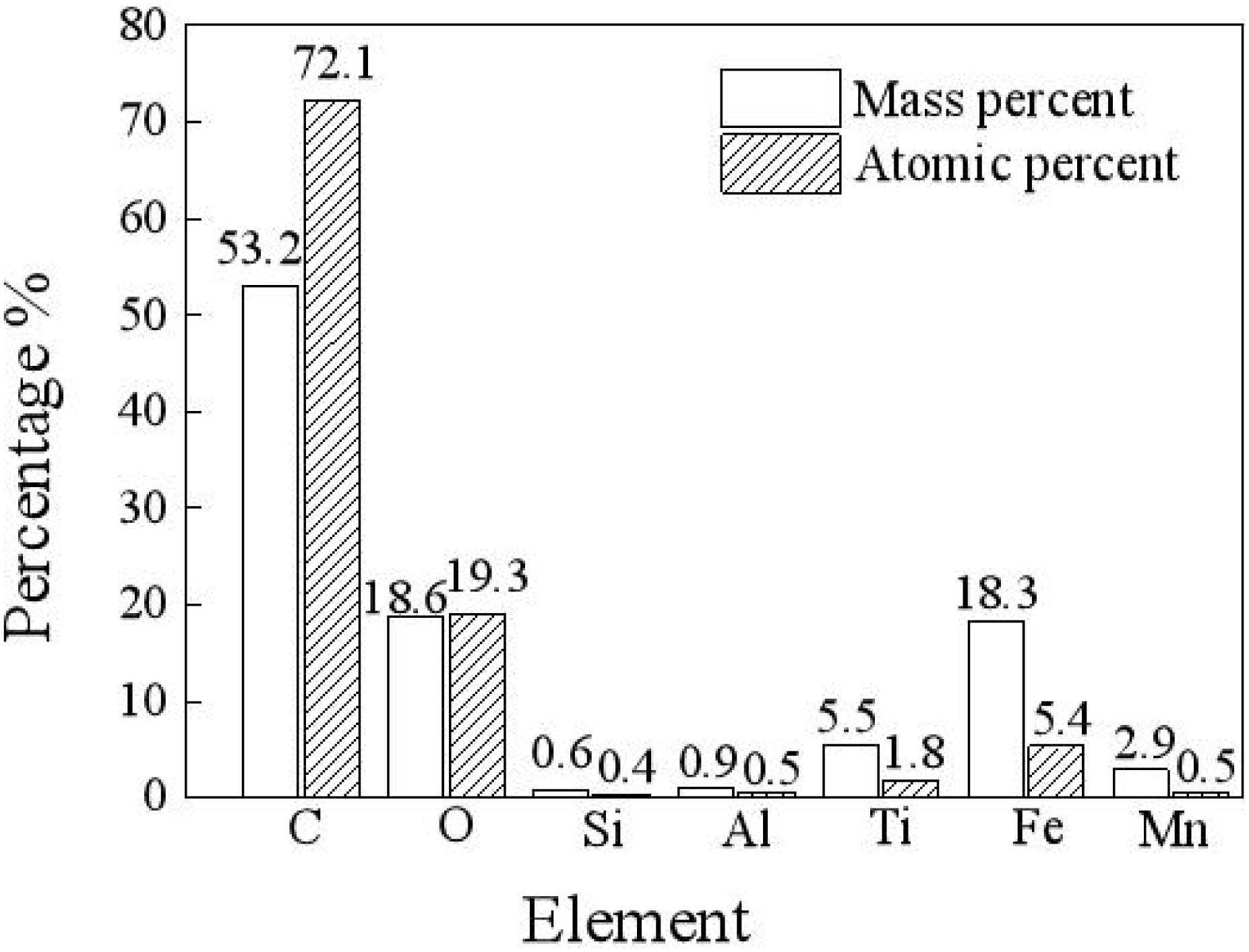
Figure 2. Diagram of composition of carbon deposition.
Spectrum of CD
An infrared spectrum analysis, as shown in Figure 3, reveals that the macromolecular compounds in the carbon deposit include hydroxyl, methyl, carbonyl, and olefin. An energy spectrum analysis of the composition of the carbon deposit reveals that some of the carbon exists in the form of methylene, which constitutes long-chain hydrocarbons, whereas some exists in the form of a carbon–carbon double bond, carbon–oxygen double bond, and methyl. Oxygen exists in the forms of hydroxyl, carbonyl, and metallic oxides. Therefore, it can be estimated that there are some functional groups, which mainly include hydroxyl, methylene, olefin, methyl, and metallic oxides. This finding suggests that, in the formation of a carbon deposit, organic chemical reactions form complex and varied substances (Wu, 2018).
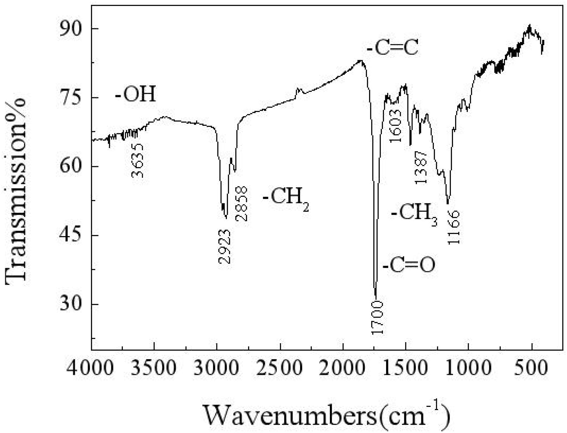
Figure 3. Infrared spectrum of a carbon deposit.
X-ray diffraction is adopted to analyze the composition of the carbon deposit. Figure 4 shows that main peaks appear when 2θ is equal to 22.36°, 27.8°, 44.2°, 54.8°, and so on. The main peak of 2θ, which is equal to 22.36°, is similar to the characteristic main peak of graphite; thus, there is a graphite-like structure in the carbon deposit. In this situation (Yoshiya et al., 2016; Zhang et al., 2020), the carbon substance is hexagonal and composed of a six-member ring. It is predicted that, in the carbon deposit, a lamella graphite structure with a hexagonal carbon ring is formed according to a certain crystallographic vector direction (Husnawan et al., 2009; Qi et al., 2020b).
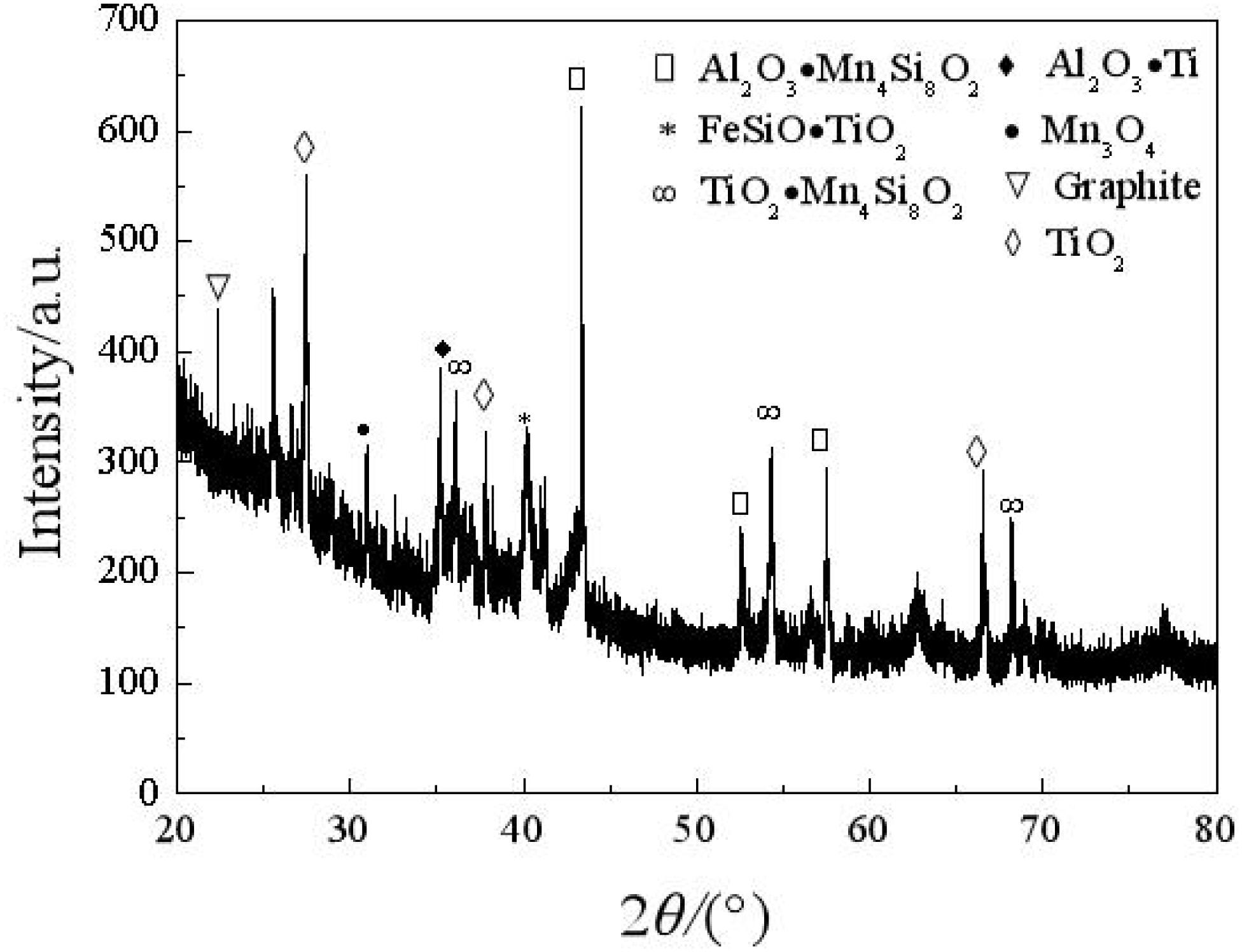
Figure 4. X-ray diffraction map of a carbon deposit.
Figure 5 shows a Raman map of a carbon deposit. There are two obvious peaks in the areas of 1,352 and 1,596 cm–1, which, respectively, represent the D vibration peak and the G vibration peak of the carbon-based material. The D vibration peak indicates the disorder and defect of element carbon material, whereas the G vibration peak represents the in-plane vibration. The ratio of D to G can be applied to evaluate the graphitization degree of the carbon substance. As shown on the map, ID/IG is equal to 0.85, which means that many defects exist in the grapheme. Coupled with the XRD map, a graphitization structure that exists in the carbon deposit is further corroborated.
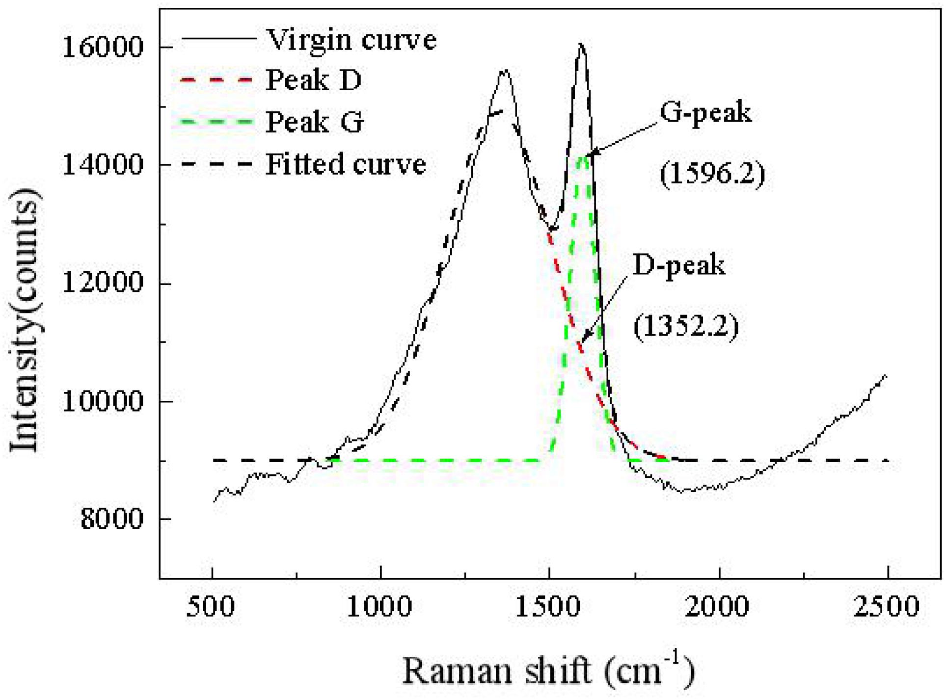
Figure 5. Raman map of carbon deposition.
Comprehensively considering the composition of the carbon deposit and when performing a maps analysis, oxidation reactions occur in the formation process, among which the oxidation of hydrocarbons dominates, where metallic particles are the catalyst.
Theory of Removing CD by Chemically Aided Magnetic Grinding
Working Mechanism of Magnetic Grinding
Because of the consistently changing magnetic field force, in the grinding container, numerous free tiny magnetic needles flip and are bound violently to grind the workpiece (Jayswal et al., 2008). By the vortex effect caused by the changing magnetic force and the CD detergent, two movement forms exist for every needle: around the axis of the grinding container and around its gravity center. When a needle bumps the workpiece at an angle, there is a scratch effect. When numerous needles collide with the workpiece many times, there will be a superposition of many plastic deformations. When the allowable plastic deformation of the material is surpassed, small chips will fall off. Thus, microgrinding is realized with a reduction in the surface roughness. When the needles are rolling on the surface of the workpiece, a tiny deformation will occur on the micropeaks of the surface, which reduces the surface roughness, whereas the surface can be hardened with improved wear resistance and fatigue strength (Jiao et al., 2015).
Figure 6 shows three kinds of contact: colliding, scratching, and rolling. When the needles contact the surface of the workpiece at a certain speed, plastic deformations will occur on the top layer of the carbon deposit. After a number of contacts, the carbon deposit will be peeled off when many contacts allow the deformation degree to exceed the plastic deformation limit. The removing effect has been obtained (Chen et al., 2018). The forces that are well distributed everywhere on the workpiece can be guaranteed by rotating the magnetic field clockwise and counterclockwise. Regarding the magnetic intensity, there exists the point effect, which means that the protruding carbon deposits will be the first to be removed by needles. When the protruding carbon deposits are peeled off gradually, the point effect will fade, which gives homogeneity (Zhou et al., 2019).
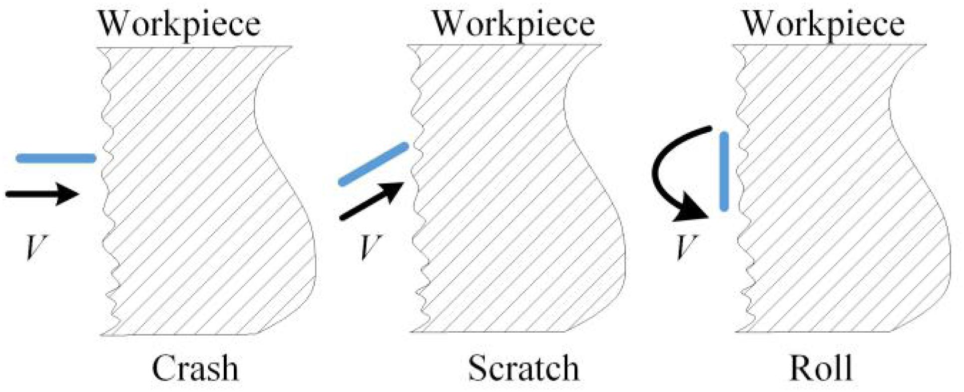
Figure 6. Theory of magnetic grinding.
Function of CD Detergent
Generally, metal detergents can be divided into two types: solvent detergent and water-based detergent. In recent years, ozone-depleting substance detergent has faced strict international restrictions because of its contamination and harmfulness; traditional petroleum detergent cannot satisfy the requirements of cleaning an aircraft surface because of its harmfulness to humans, contamination of the environment, and low flash point (Zhang and Han, 2014; Guo et al., 2019). Conversely, water-based detergent has many advantages due to its nonharmfulness, noncontamination, high flash point, strong cleaning ability, and wide range of application. Water-based detergent causes no damage or corrosion of the cleaned item and is suitable for high-pressure and ultrasonic cleaning and cleaning an engine compressor offline and online (Abdallah et al., 2018; Qi et al., 2020a).
As shown in Figure 7, in certain conditions, when water-based detergent contacts dirt, the amphiphilic surfactants in the detergent, which adhere to the surface of the grease dirt, reduce the interfacial tension between grease and water. The surfactants rise to the interface and reduce the adhesion between grease and metal via oriented absorption. By a series of actions, such as madefaction, emulsification, dispersion, and solubilization, combining physical ways, such as heating, scrubbing, flushing, and ultrasonic wave, the dirt can be more quickly removed and dispersed into the detergent from the workpiece (Stancu et al., 2016; Li et al., 2020; Liu et al., 2020).
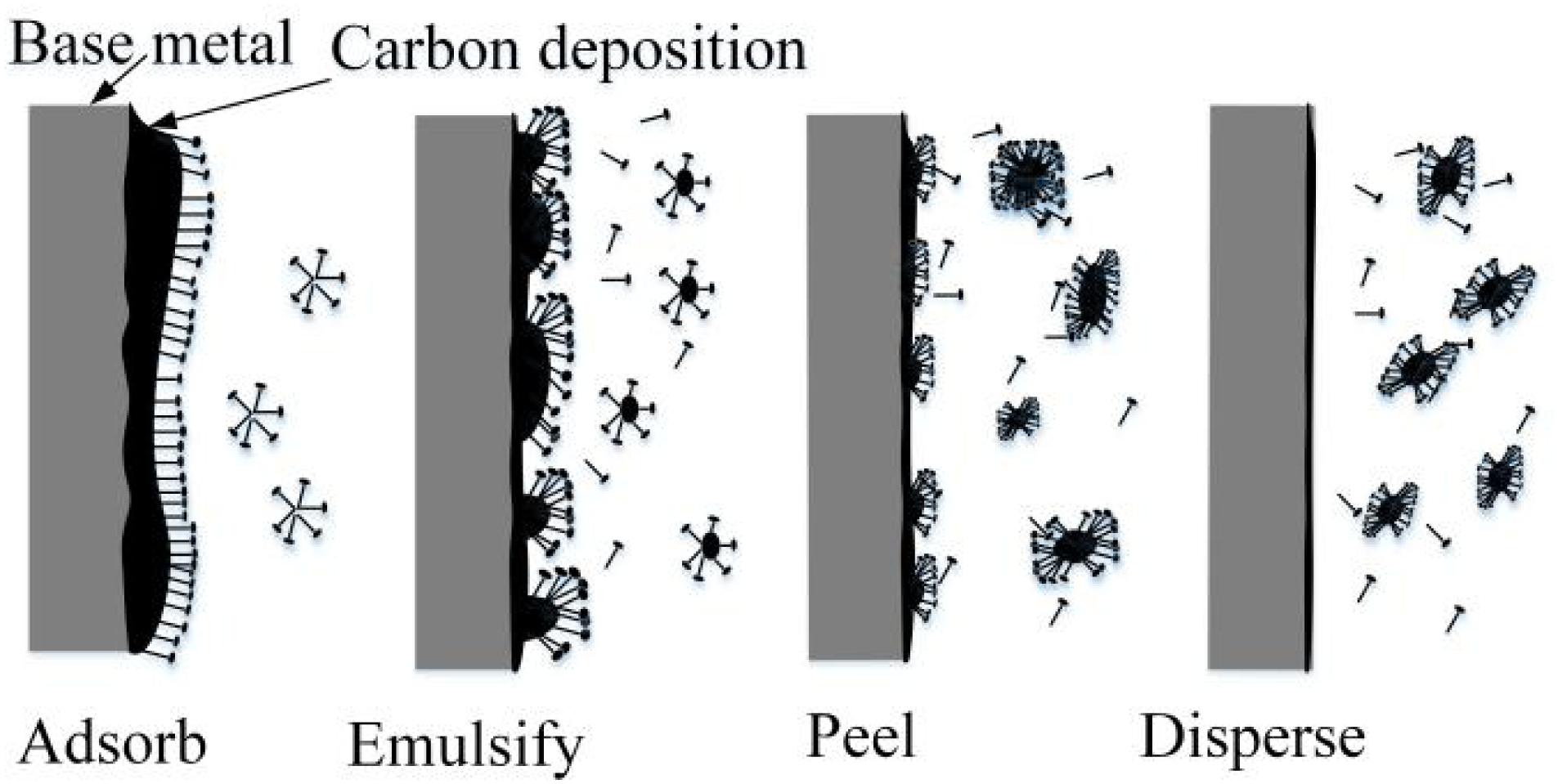
Figure 7. Removing mechanism of CD detergent.
Removing Mechanism of Chemically Aided Magnetic Grinding
The carbon deposit on the inner surface of the turbo shaft, which is cemented and hardened, sticks to the base metal with a thickness of 1–2 mm and cannot be removed completely with detergent. Therefore, CAMG is proposed to remove the compacted carbon deposit with high efficiency. By drenching the turbo shaft into the detergent, the cohesion between the carbon deposit and the base metal can be reduced by actions of the surfactants, which soften the top layer of the carbon deposit via madefaction, emulsification, dispersion, and solubilization. The carbon deposit, which is collided, scratched, and rolled by the magnetic needles driven by the rotating magnetic field, will be peeled off the base metal at a faster rate (Liu et al., 2015). Combined with magnetic grinding, the detergent will also saturate the deeper layers, which causes emulsification of the deeper carbon deposit. By the interaction of magnetic grinding and the detergent, the carbon deposit will be removed entirely and more quickly (Inagaki et al., 2005; Garnweitner and Niederberger, 2006).
Experiment Research
Experiment Equipment
As shown in Figure 8, a translational permanent magnetic grinding machine, which is researched and developed independently, which is composed of a grinding container, magnetic disk, spring, motor controlling system, and so on, is selected for the experiment. On the rotating plate, neodymium magnets are placed according to a certain rule. The magnetic disk is driven by the motor to form the changing magnetic force. On the pole plate, the N-pole and S-pole are distributed alternatively using the same circumference. The workpiece is put into the grinding container with the CD detergent submerging it. Parameters, such as the rotating speed of the poles on the disk, process time, reciprocating speed of the magnetic disk, and so on, can be adjusted. The grinding effect can be affected by many factors, among which the needle type, process time, and processing space are the major factors.
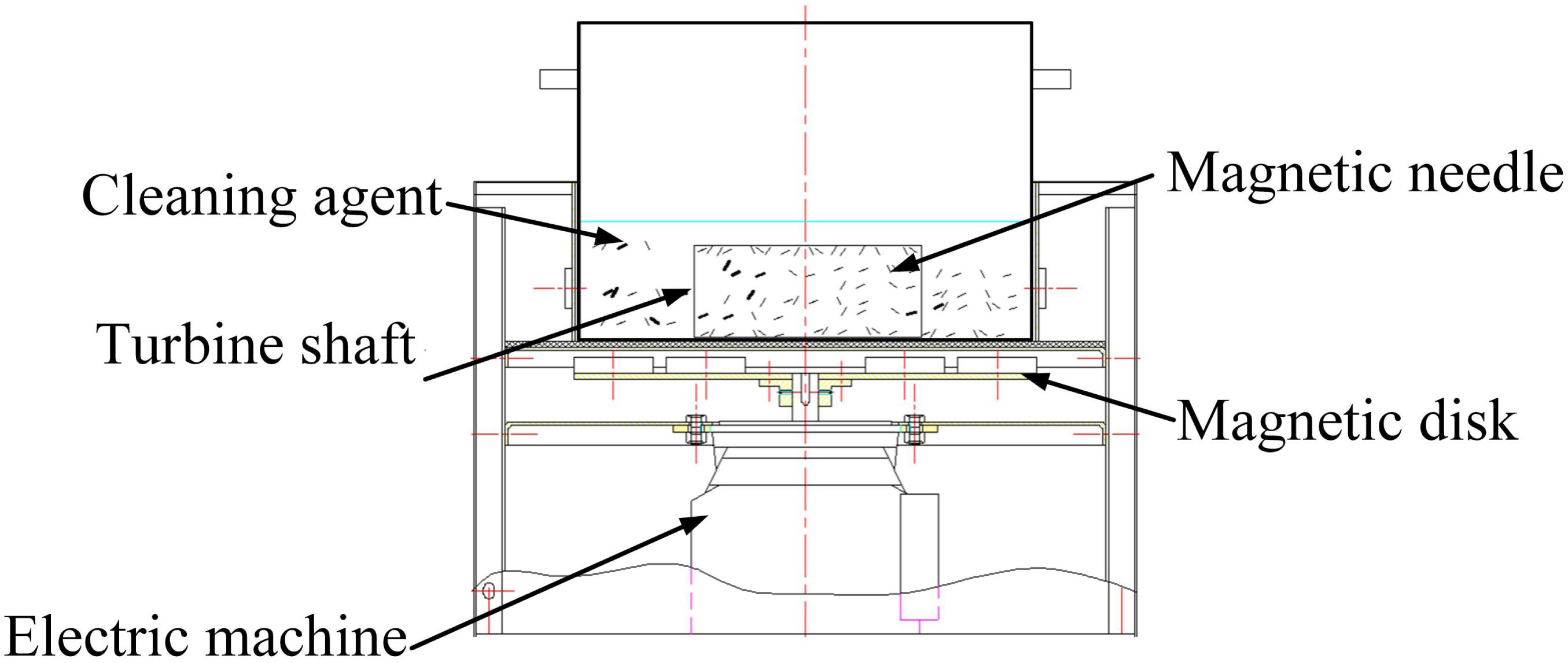
Figure 8. Processing sketch.
In the experiment, the adopted needles are fabricated of 304 stainless steel and are cylindrical and magnetized. There are many different types of needles in terms of diameter. With a constant magnetic field intensity, the type of magnetic needle determines the magnetic force. If the type is too small, the magnetic force is correspondingly weak. The collision, scratches, and rolling on the surface of the workpiece are not enough to present the grinding effect. If the type is too big, the magnetic force is accordingly strong. When the material of the workpiece is soft, the surface of the workpiece will be damaged by overgrinding.
When the processing time is too short, the collision, scratches, and rolling on the surface of the workpiece by the needles is insufficient. As a result, the microstructure of the workpiece will be seldom improved, and the surface undergoes minimal intensification due to an insufficient number of microplastic deformations. When the processing time is too long, energy will be wasted, and the processing efficiency will be low. Sometimes there may be unnecessary damage to the workpiece (Li et al., 2010; Wu et al., 2015).
The changing frequency of the magnetic field is determined by the rotating speed of the magnetic disk. When other parameters remain constant, the movement track of a needle grows more complex as the disk’s rotating speed increases. Better surface quality can be ensured by increasing the frequency of contact between the needles and the workpiece (Zou et al., 2011; Xu et al., 2020b).
The processing magnetic distance, which is the distance between the magnetic disk and the grinding container, determines the forces of the needles generated by the magnetic field. According to experience, the processing distance is set to 20 mm (Zhou et al., 2015).
Table 1 shows the parameters for the experiment.
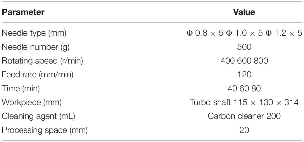
Table 1. Experiment parameters.
Experiment Conditions
(1) Test of surface features. VHX-500F (a super field three-dimensional electron microscope) and JB-08E (a surface roughness meter) are adopted to observe the microstructure and measure the surface roughness before and after grinding. HV-1000 (a microhardness tester), and X-ray stress analyzer is selected to test the surface microhardness and residual stress before and after grinding.
(2) Evaluation method for the carbon deposit removal ratio. There are numerous ways to estimate the surface clearness of a metal part. Based on its property and the contaminations on it, the selected testing method should be accurate and easily operational, scientific and reasonable. Currently, the main testing method is Blue-Ray detection combined with visual inspection. However, the whole process is neither objective nor accurate (Lee et al., 2015). In this article, the area percentage of the carbon deposit on the inner surface before and after grinding is selected to estimate the surface clearness. A single lens reflex camera is employed to take pictures in the shaft before and after grinding. MATLAB is utilized to quantize the carbon deposit in the image and separate it from the base metal by conducting clustering segmentation, image enhancement, image binarization, expansion and corrosion, and calculation of the area of CD (Du and Zhao, 2016; Xu et al., 2020a).
Optimizing Process Parameters
Process Parameters
To investigate the optimum process parameters for magnetic grinding, based on the preceding work, response surface analysis is adopted with the speed of the magnetic field, process time, and needle type as the main influence factors. A three-factor and three-level experiment plan is designed. Each of the factors has the value range shown in Table 2.
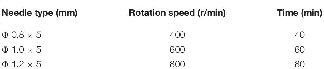
Table 2. Group parameters of response surface.
Response surface analysis is employed to fit values of the experimental points. Combining Design-Expert modeling and linear regression equation, the interactive influence relationship between every two factors can be obtained. The linear regression equation is expressed as follows:
The value of R2 is 0.9859, which is approaching 1.0; that is, the reliability of the mathematical model fitted by Design-Expert for the surface roughness is excellent with a high fitting degree. The value of Pr > F is 0.0001, which is much less than 0.5 and means that the three selected factors have significant impacts on the surface roughness.
Interaction Between Needle Type and Rotating Speed of the Magnetic Field
Figure 9A shows the interaction diagram of the needle type and rotating speed of the magnetic field when the grinding time is 60 min. When the needle type and rotating speed of the magnetic field are both increasing, the surface roughness will initially decrease and then increase. When the rotating speed of the magnetic field is 400 r/min, the needles move slowly relative to the cylinder wall. Within the unit time, the amounts of collision, scratching, and rolling are insufficient, which produces a low-quality surface and decreases the surface roughness. When the rotating speed of the magnetic field increases to 800 r/min, the needles move much more violently per unit time. The actions on the workpiece by the needles increase to make the movement tracks of the needles repeatedly and iteratively act on the surface, which produces deep scratches with high surface roughness. By experiments, the best effect can be obtained when the rotating speed is 600 r/min, and the type of needle is Φ 1.0 × 5 mm.
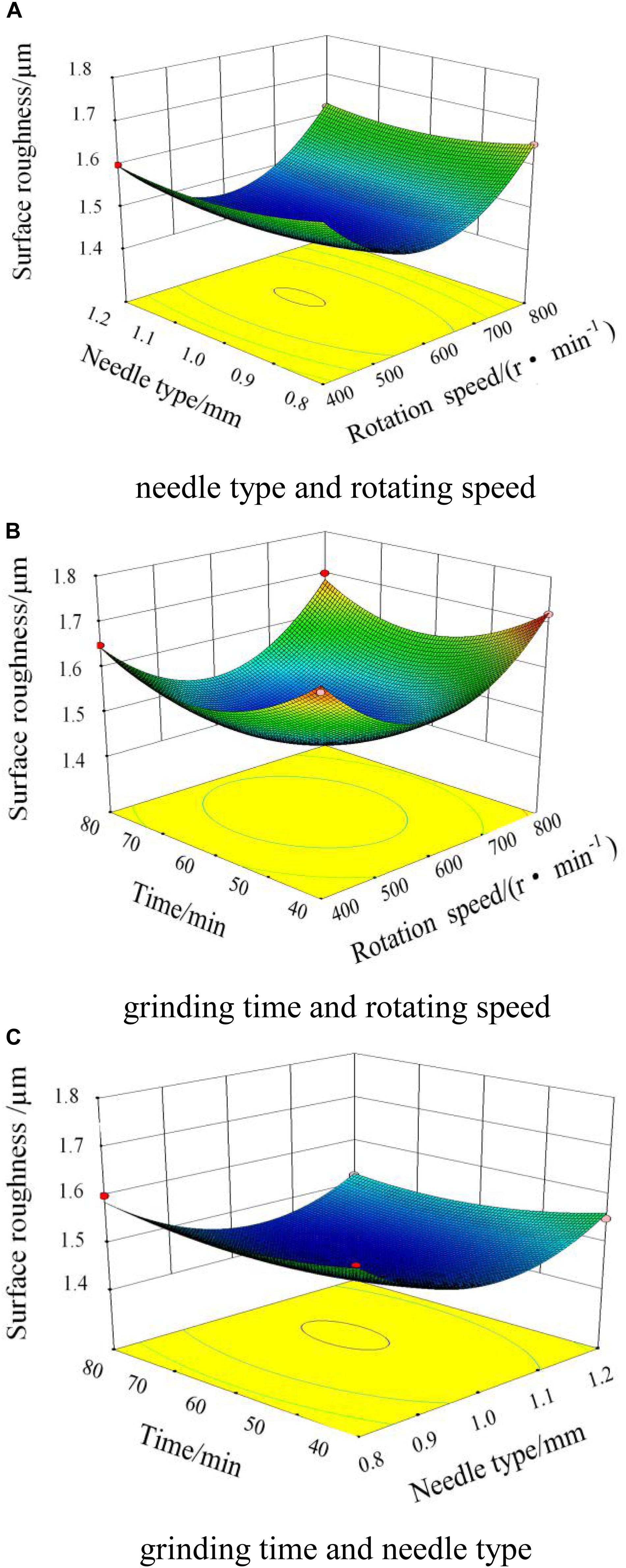
Figure 9. Interaction diagram of the magnetic field. (A) Needle type and rotating speed. (B) Grinding time and rotating speed. (C) Grinding time and needle type.
Interaction Between Grinding Time and Rotating Speed of the Magnetic Field
Figure 9B shows the interaction between the grinding time and the rotating speed of the magnetic field when the needle type is Φ 1.0 × 5 mm. When the grinding time is in the range of 0–60 min, the surface roughness decreases very quickly. When the grinding time increases to 60 min, the surface roughness reaches the lowest value. As the grinding time increases continuously, on the surface of the workpiece, the scratches exacerbate with an increase in surface roughness.
Interaction Between Grinding Time and Needle Type
Figure 9C shows the interaction between the grinding time and the needle type when the rotating speed of the magnetic field is 600 r/min. As the grinding time and the diameter of the needle increase, and the surface roughness decreases and then increases. When the needle type is Φ 1.0 × 5 mm and the grinding time is 60 min, the lowest surface roughness is obtained. Comprehensively analyzing the influence factors, the optimum combination of process parameters can be obtained: the rotating speed of the magnetic field is 600 r/min, the needle type is Φ 1.0 × 5 mm, and the grinding time is 60 min.
Microstructure and Surface Roughness
Figure 10 shows comparison pictures of the microstructure on the workpiece after magnetic grinding and CAMG. Figure 10A shows the original microstructure. Figure 10B shows the microstructure after magnetic grinding. Figure 10C shows the microstructure after CAMG. The original surface, which is almost covered by carbon, is so uneven that the surface roughness cannot be measured. After 60 min of magnetic grinding, which is shown in Figure 10B, most of the deposited carbon has been removed, and the base metal appears. As shown in Figure 10C, by 60 min, CAMG not only causes the base metal to appear but also obviously increases the removing efficiency.
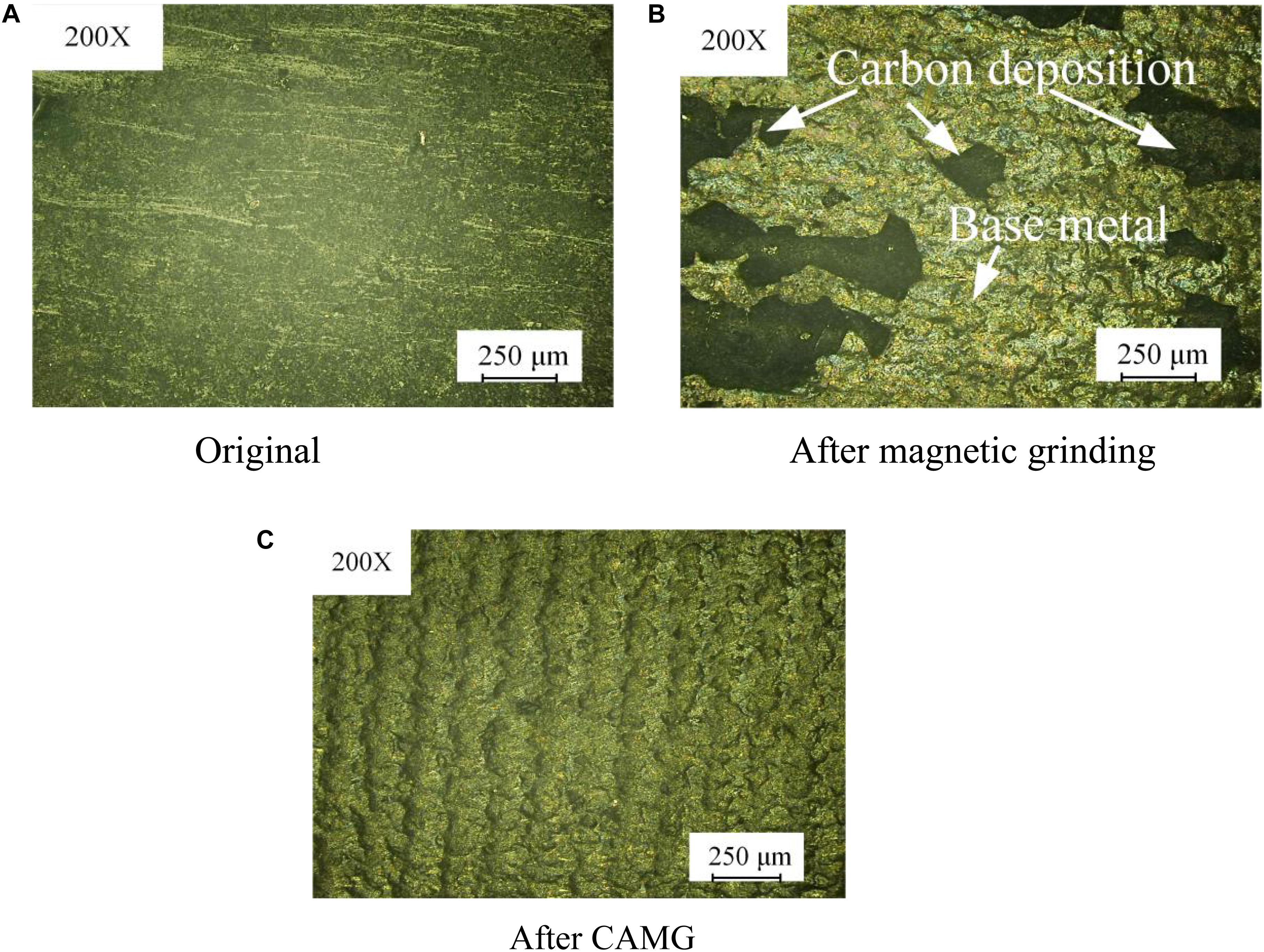
Figure 10. Comparison of the microstructure on the workpiece. (A) Original. (B) After magnetic grinding. (C) After CAMG.
Figure 11 shows the comparison curves of the surface roughness after magnetic grinding and CAMG. With the same grinding time of 60 min, the surface roughness after CAMG is 1.47, whereas that after magnetic grinding is 2.16. By CAMG, in addition to the increase in the removing efficiency, the surface quality has been improved obviously.
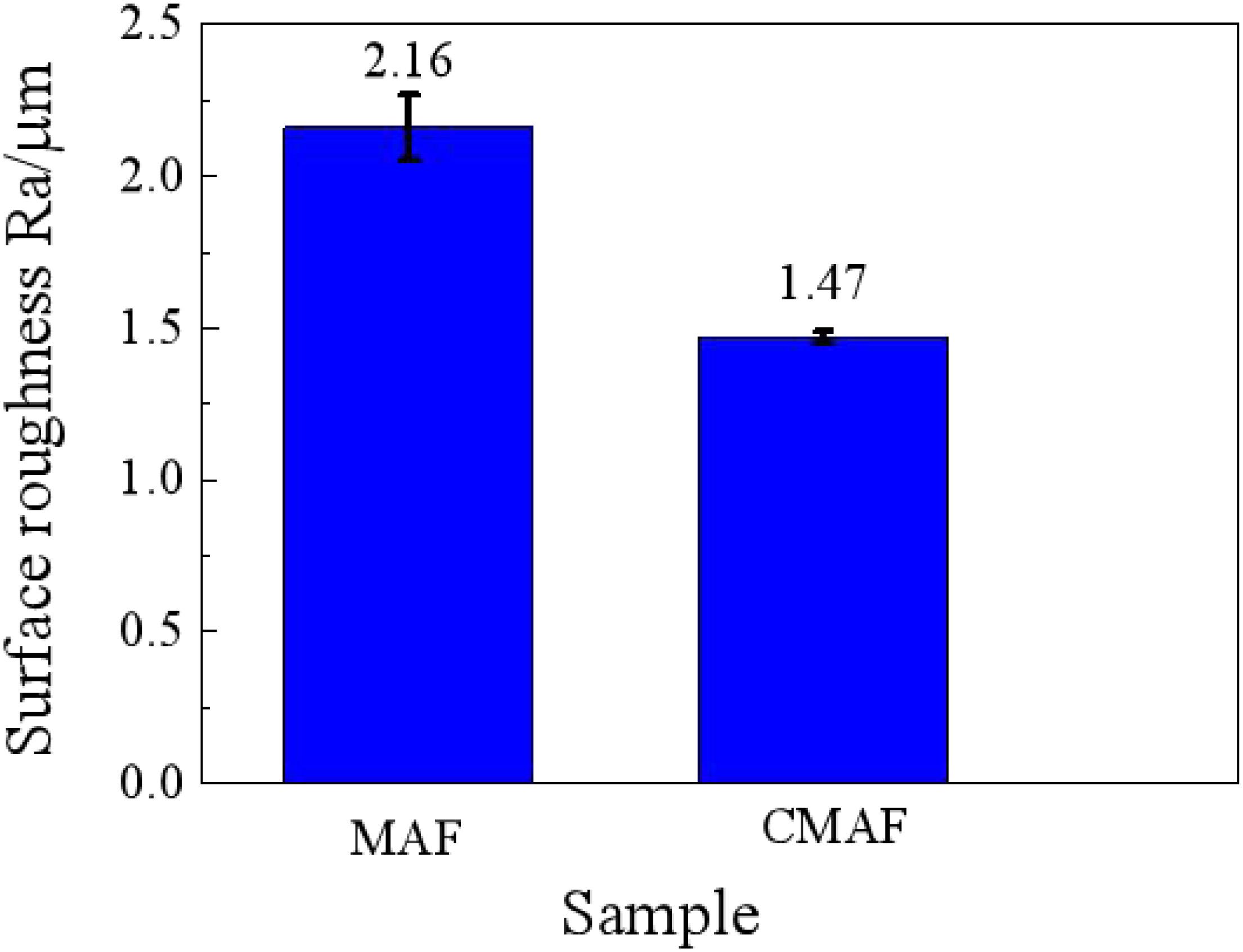
Figure 11. Comparison of surface roughness.
Scanning electron microscopy is employed to observe the surface of the workpiece shown in Figure 12. As shown in Figure 12A, on the surface of the base metal before grinding, there is thick carbon deposit. After 40 min of grinding, part of the carbon deposit is removed, as shown in Figure 12B. As shown in Figure 12C, after 60 min, the carbon deposit has been removed entirely, and metal luster presents with few scratches on the surface.
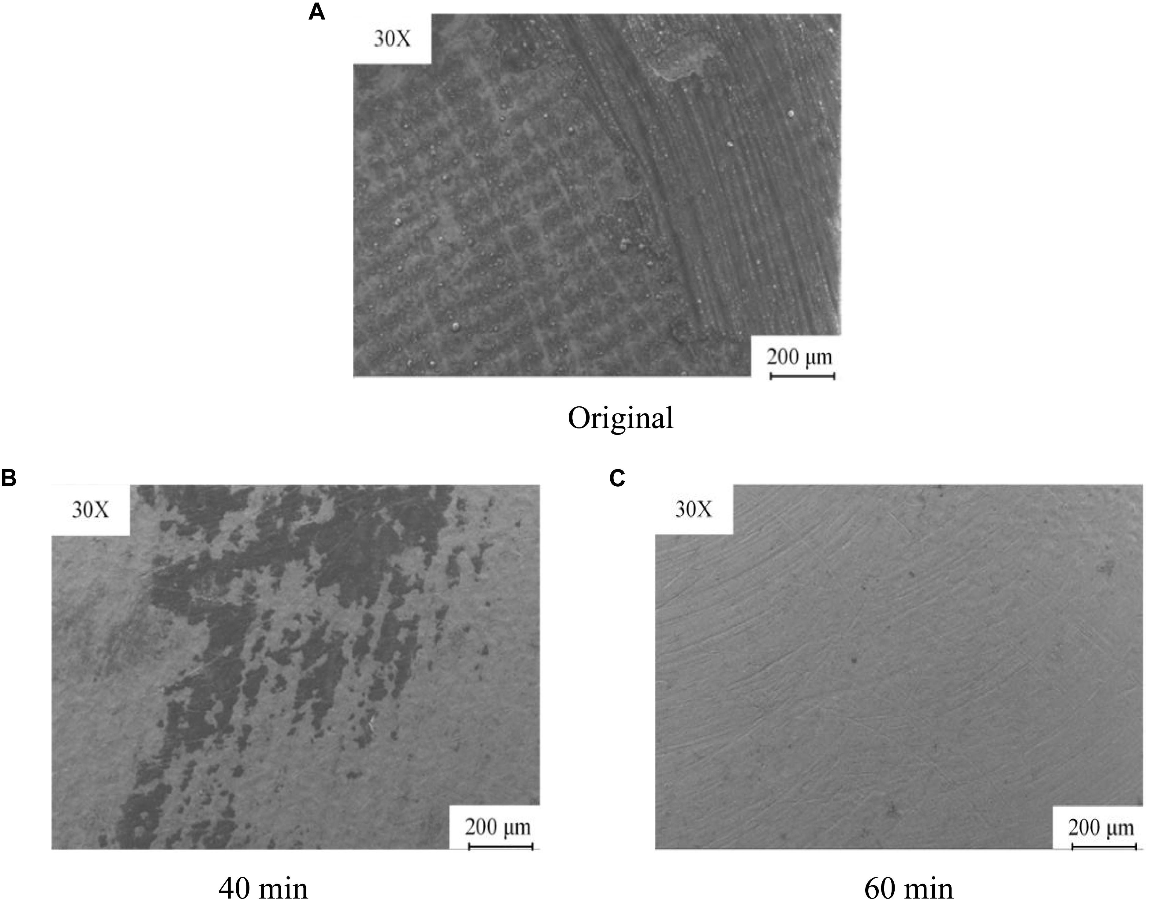
Figure 12. Microstructure after CAMG. (A) Original. (B) 40 min. (C) 60 min.
Residual Stress
On the surface of the workpiece, six points are selected to test the stress interplanar spacing. The residual stress can be calculated as follows:
In the formula, σ is residual stress, MPa; υ is Poisson ratio the material; ψ is tilting angle; E is modulus of elasticity of the material, GPa; φ is diffraction angle; dφ is tilting interplanar spacing, μm; dn is the plastic deformation spacing of the initial surface on the crystal material at the initial tilting angle due to preliminary processing, μm.
As shown in Figure 13, the residual stress on the material original surface, which is affected by the plastic deformation and processing temperature during preliminary processing, is tensile with a value of +49 MPa. After magnetic grinding, the residual stress decreases obviously to -86 MPa, which means compressive stress, as the residual stress has been released after the surface is repeatedly impacted by the magnetic needles when the carbon deposit is removed.
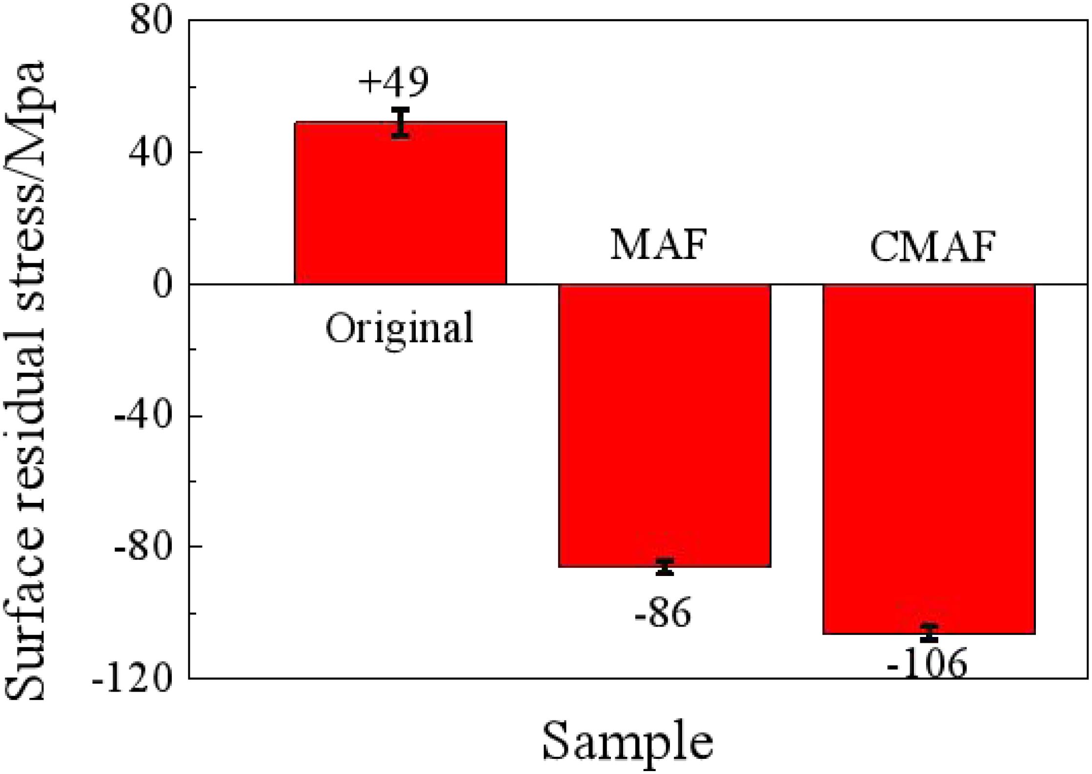
Figure 13. Comparison of residual stress.
On the surface processed by CAMG, the residual stress decreases significantly to −106 MPa and is also compressive due to the frictions of the magnetic needles and lubrication of the detergent. The residual compressive stress can effectively improve the ability to resist fatigue, stress corrosion, and creep cracking. The surface has been improved obviously (Zhu and Zhang, 2014).
Carbon Deposition Removal Ratio
Figure 14 shows the comparison pictures taken by a camera and processed by MATLAB via a series of operations, namely, clustering segmentation, image enhancement, image binarization, and expansion and corrosion. Figure 14A shows the original picture after grinding. Figure 14B shows the picture after clustering segmentation and intensification by the Retinex algorithm. Binarization is performed to turn the carbon deposit black and turn the base metal and background white by setting the gray value of the pixel to 0 or 255. Binarization enables the number of black pixels that represent deposited carbon to be calculated more easily. In the morphological calculation for images, image expanding and corroding are performed to increase and decrease the number of pixels around the objective area based on the structure factors and dimensions. Image expanding can make the objective area expand to some extent. Figure 14C shows that the picture is divided into two parts: the first part is black and represents deposited carbon with the gray value of pixels set to 0, whereas the second part is white and represents the background and the base metal with the gray value of pixels set to 1. By calculating the number of black pixels in the images of the workpiece before and after cleaning, the carbon deposition removal ratio can be obtained.
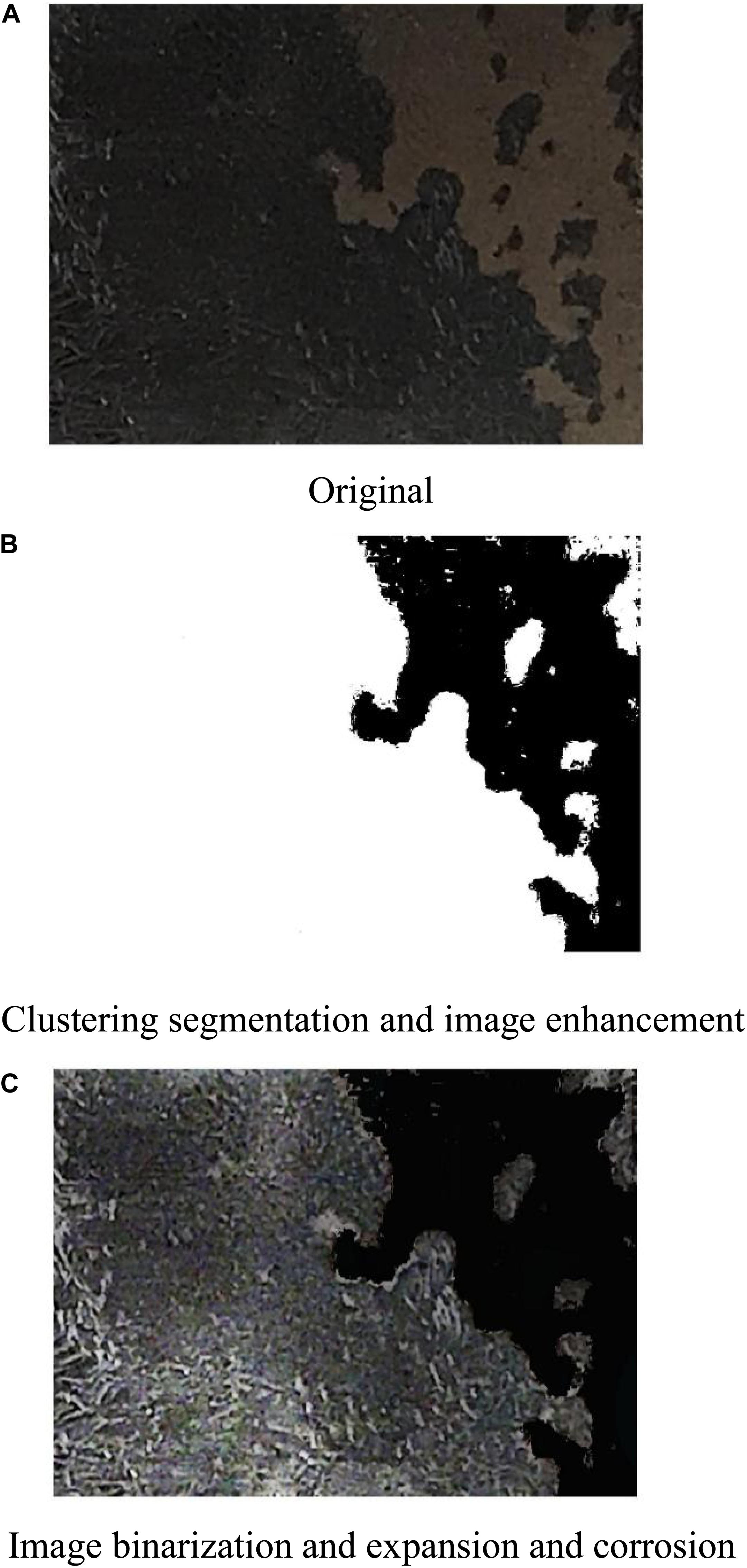
Figure 14. Process of image manipulation by MATLAB. (A) Original. (B) Clustering segmentation and image enhancement. (C) Image binarization and expansion and corrosion.
Figure 15 shows a comparison diagram of the removal ratios between magnetic grinding and CAMG. After 60 min, both methods can effectively remove deposited carbon with removal ratios greater than 80%. CAMG has a higher efficiency with a removal ratio of 98% and satisfies the reapplication requirements.
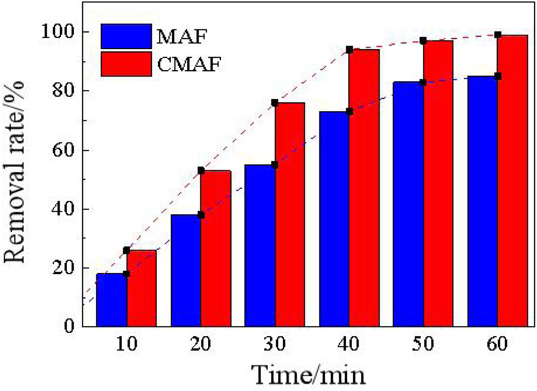
Figure 15. Comparison diagram of the removal ratios.
Conclusion
1. For the problem of removing carbon deposited on the inner surface of a large-scale turbo shaft of an aeroengine with high efficiency and low damage, chemically aided magnetic grinding is proposed. By magnetic force, the magnetic needles collide, scratch, and roll on the workpiece with high frequency to achieve the purpose of microcutting. Thus, the removing effect is obtained.
2. SEM, XRD, FTIR, and Raman spectroscopy are adopted to analyze carbon deposits, in which, by preliminary judgment, there exist functional groups such as hydroxyl, methylene, alkene, methyl, and sulfur compounds, which are formed by a series of actions, such as fracture, oxidation, and accumulation. In the production of the carbon deposit, many organic chemical reactions occur, in which aromatics and cycloalkanes have been oxidized, cracked, pyrolyzed, coked, and polymerized on the inner surface of the turbo shaft. Thus, complex and diverse substances, which are mainly composed of graphitized carbon, colloids, and oxides, are produced.
3. A translational permanent magnet grinding machine, which is designed and developed independently, is adopted to conduct an experiment for removing the carbon deposited on the inner surface of the turbo shaft. By experiments and interaction analysis, the best removing effect can be obtained with a rotating speed of the magnetic field of 600 r/min, a needle type of Φ 1.0 × 5 mm, a grinding time of 60 min, and a surface roughness of Ra 1.8 μm.
4. Chemically aided magnetic grinding is adopted to conduct the research. Amphiphilic surfactant in the detergent can reduce the adhesion between the carbon deposit and the surface of the base metal. By a series of chemical actions, such as madefaction, emulsification, dispersion, and solubilization, and combining physical actions of collision, scratching, and rolling, the carbon deposit can be peeled off the metal surface at a faster rate.
5. The comparison experiments verify that, against the single magnetic grinding, chemically aided magnetic grinding can remove the stubborn carbon deposit with a higher efficiency. After 60 min of grinding, 98% of the carbon deposit has been removed, and the residual stress is -106 MPa. The surface quality has been improved obviously and satisfies the requirements of reapplication.
Data Availability Statement
All datasets generated for this study are included in the article.
Author Contributions
HX did experiments, wrote the manuscript, and participated in the experimental design. RK did experimental design. XZ did the spectrum test which include XRD, Raman, and gave some writing guidance. LL was involved in research guidance and test results discussion and demonstration. LW participated in the workpiece measurement and test plan design. YC was the leader of project and participated in the experimental design. All authors contributed to the article and approved the submitted version.
Funding
This study was co-supported by the National Natural Science Foundation of China (51775258) and the Key Laboratory of Precision and Special Processing Ministry of Education (201703).
Conflict of Interest
LL and LW were employed by the company AECC XI’AN AERO-ENGINE LTD.
The remaining authors declare that the research was conducted in the absence of any commercial or financial relationships that could be construed as a potential conflict of interest.
References
Abdallah, M., Hegazy, M. A., Alfakeer, M., and Ahmed, H. (2018). Adsorption and inhibition performance of the novel cationic gemini surfactant as a safe corrosion inhibitor for carbon steel in hydrochloric acid. Green Chem. Lett. Rev. 11, 457–468. doi: 10.1080/17518253.2018.1526331
Chen, Y., Zeng, J., Hu, Y., and Wu, C. (2018). Ultrasonic assisted magnetic abrasive finishing special-shaped pipe of nickel based alloy GH4169. China Surf. Eng. 31, 118–124.
Du, M., and Zhao, X. (2016). Face enhancement algorithm with variable illumination based on improved retinex. Comput. Sci. 43, 105–108, 112.
Garnweitner, G., and Niederberger, M. (2006). Nonaqueous and surfactant-free synthesis routes to metal oxide nanoparticles. J. Am. Ceram. Soc. 89, 1801–1808. doi: 10.1111/j.1551-2916.2006.01005.x
Guo, J., Au, K. H., Sun, C., Goh, M. H., Kum, C. W., Liu, K., et al. (2019). Novel rotating-vibrating magnetic abrasive polishing method for double-layered internal surface finishing. J. Mater. Process. Technol. 264, 422–437. doi: 10.1016/j.jmatprotec.2018.09.024
Hao, L. (2016). Research on the Ultrasonic Cleaning Technology of Aero-Engine Low Pressure Turbine Shaft. Ph.D. thesis, Dalian university of technology, Dalian.
Huang, Y., Zhu, Y., Xiong, C., and Pan, Y. (2011). The nature of the aeroengine nozzle coking carbon. J. Beijing Univ. Aeronaut. Astronaut. 5, 753–756. doi: 10.13700/j.bh.1001-5965.2011.06.015
Husnawan, M., Masjuki, H. H., Mahlia, T. M. I., and Saifullah, M. G. (2009). Thermal analysis of cylinder head carbon deposits from single cylinder diesel engine fueled by palm oil-diesel fuel emulsions. Appl. Energy 86, 2107–2113. doi: 10.1016/j.apenergy.2008.12.031
Inagaki, Y., Suzumura, A., Lkeshoji, T. T., and Yamazaki, T. (2005). Cleaning effect of interlayer metal on thejoining surface during braze pressure welding. JSME Int. J. Ser. A 48, 413–419. doi: 10.1299/jsmea.48.413
Jayswal, S. C., Jain, V. K., and Dixit, P. M. (2008). Magnetic abrasive finishing process-a parametric analysis. J. Adv. Manuf. Syst. 4, 131–150. doi: 10.1142/S0219686705000655
Jia, W. (2005). The Study of the Remanufacturing Cleaning Technology for a Fighter’s Parts. Ph.D. thesis, Dalian University of Technology, Dalian.
Jiang, J., Shen, H., and He, Y. (2017). The discuss of carbon deposition treament new technology method about car engines. Equip. Manuf. Technol. 4, 155–157.
Jiao, A. Y., Quan, H. J., Li, Z. Z., and Chen, Y. (2015). Study of magnetic abrasive finishing in seal ring groove surface operations. Int. J. Adv. Manuf. Technol. 85, 1195–1205. doi: 10.1007/s00170-015-8029-7
Kauffman, R. E., Feng, A. S., and Karasek, K. R. (2000). Coke formation from aircraft engine oils: part II-effects of oil formulation and surface composition. Tribol. Trans. 43, 677–680. doi: 10.1080/10402000008982395
Lee, Y., Wu, K., Bai, C., Liao, C., and Yan, B. (2015). Planetary motion combined with two-dimensional vibration-assisted magnetic abrasive finishing. Int. J. Adv. Manuf. Technol. 76, 1865–1877. doi: 10.1007/s00170-014-6370-x
Li, F., Zhu, Y., Huang, Y., and Liu, Y. (2014). Anti-coking performance of nozzle material’s surface chemical modification. J. Beijing Univ. Aeronaut. Astronaut. 40, 564–568. doi: 10.13700/j.bh.1001-5965.2013.0326
Li, H., Zou, X., Wei, H., Li, Q., Gao, Q., Liu, Q., et al. (2020). SiO2 coated on ZnO nanorod arrays with UV-durable superhydrophobicity and highly transmittance on glass. Front. Chem. 8:101. doi: 10.3389/fchem.2020.00101
Li, L., Wang, Z., Huang, T., Xie, J., and Qi, L. (2010). Porous gold nanobelts templated by metal-surfactantcomplex nanobelts. Langmuir 26, 12330–12335. doi: 10.1021/la1015737
Liu, S., Yan, P., Li, H., Zhang, X., and Sun, W. (2020). One-step microwave synthesis of micro/nanoscale LiFePO4/graphene cathode with high performance for lithium-ion batteries. Front. Chem. 8:104. doi: 10.3389/fchem.2020.00104
Liu, W., Li, M., Short, T., Qing, X., He, Y., Li, Y., et al. (2015). Supercritical carbon dioxide cleaning of metal parts for remanufacturing industry. J. Clean. Prod. 93, 339–346. doi: 10.1016/j.jclepro.2015.01.014
Liu, Z., Wang, J., and Lin, Y. (2014). Study on the causes and countermeasures of intake valve deposit of gasoline drect injection engine. Int. Combust. Eng. 3, 54–57.
Qi, K., Lv, W., Khan, I., and Liu, S. (2020a). Photocatalytic H2 generation via CoP quantum-dot-modified g-C3N4 from electroless plating. Chin. J. Catal. 41, 114–121. doi: 10.1016/S1872-2067(19)63459-5
Qi, K., Xing, X., Zada, A., Li, M., Wang, Q., Liu, S., et al. (2020b). Transition metal doped ZnO nanoparticles with enhanced photocatalytic and antibacterial performances: experimental and DFT studies. Ceram. Int. 46, 1494–1502. doi: 10.1016/j.ceramint.2019.09.116
Stancu, C., Alegre, D., Ionita, E. R., Mitua, B., Grisoliar, C., Tabares, F. L., et al. (2016). Cleaning of carbon materials from flat surfacesand castellation gaps by an atmospheric pressure plasma jet. Fusion Eng. Des. 103, 38–44. doi: 10.1016/j.fusengdes.2015.12.024
Tumuluri, S., Murugeshan, P., Mishra, R. K., and Subrahmanyam, V. V. (2017). Application of direct metal deposition process for failure prevention of oil pump gear shaft in an aero engine. J. Fail. Anal. Prevent. 17, 788–795. doi: 10.1007/s11668-017-0289-0
Wang, X., Jia, X., Li, F., Yang, M., Zhang, J., and Sun, Y. (2017). The research on formation mechanism of carbon deposition in remanufacturing engines. Chin. J. Mech. Eng. 53, 69–75. doi: 10.3901/JME.2017.05.069
Wu, J., Zou, Y., and Sugiyama, H. (2015). Study on ultra-precision magnetic abrasive finishing process using low frequency alternating magnetic field. J. Magn. Magn. Mater. 386, 50–59. doi: 10.1016/j.jmmm.2015.03.041
Wu, Y. (2018). Pyrolysis and Coking Kinetics and the Effects Mechanism During the Pyrolysis Process of n-Heptane. Ph.D. theissi, University of Chinese Acadeny of Sciences, Huairou District.
Xu, H., Kang, R., and Chen, Y. (2020a). Experimental study on removing carbon from fuel nozzles by magnetic grinding. Acta Aeronaut. Astronaut. Sin. 41:623505. doi: 10.7527/S1000-6893.2019.23505
Xu, H., Kang, R., Liu, D., and Chen, Y. (2020b). Experimental analysis of removal inner surface carbon from aero-engine turboshaft by magnetic grinding. Surf. Technol. 49, 336–342. doi: 10.16490/j.cnki.issn.1001-3660.2020.01.040
Yao, S., Jia, X., Wang, X., Li, J., and Li, J. (2015). Molten salt cleaning process of carbon deposition on engine valve. China Surf. Eng. 28, 121–126. doi: 10.11933/j.issn.1007-9289.2015.04.016
Yoshiya, M., Ono, K., Dewa, K., Watanabe, A., Saito, Y., Matsushita, Y., et al. (2016). Reaction pathway for nascent soot in ethylene pyrolysis. Combust. Flame 167, 248–258. doi: 10.1016/j.combustflame.2016.02.008
Zhang, S., Khan, I., Qin, X., Qi, K., Liu, Y., and Bai, S. (2020). Construction of 1D Ag-AgBr/AlOOH plasmonic photocatalyst for degradation of tetracycline hydrochloride. Front. Chem. 8:117. doi: 10.3389/fchem.2020.00117
Zhang, Y., Ni, D., Lee, I., Lin, D., and Yang, Z. (2018). Test on hot jet noise of scaled engine nozzle. Acta Aeronaut. Astronaut. Sin. 39, 145–155. doi: 10.7527/S1000-6893.2018.22446
Zhang, Z., and Han, L. (2014). Application of component-remanufactured cleaning technology. Clean. World 30, 42–45.
Zhou, C., Han, B., Xiao, C., Chen, Y., and Liu, X. (2019). Application of magnetic abrasive particle aided magnetic needles grinding. Surf. Technol. 48, 275–282. doi: 10.16490/j.cnki.issn.1001-3660.2019.03.037
Zhou, K., Chen, Y., Du, Z. W., and Niu, F. L. (2015). Surface integrity of titanium part by ultrasonic magnetic abrasive finishing. Int. J. Adv. Manuf. Technol. 80, 997–1005. doi: 10.1007/s00170-015-7028-z
Zhu, A., and Zhang, X. (2014). Application of MATLAB in underwater laser line scan image processing. J. Atmos. Environ. Opt. 9, 391–396. doi: 10.3969/j.issn.1673-6141.2014.05.009
Keywords: carbon deposition, chemically assisted magnetic grinding, surface roughness, aluminum alloy tube, oscillator frequency
Citation: Xu H, Kang R, Zhu X, Liu L, Wang L and Chen Y (2020) Study and Analysis of Removing the Carbon Deposition on the Inner Surface of a Turbo-Shaft by Chemically Assisted Magnetic Grinding. Front. Mater. 7:232. doi: 10.3389/fmats.2020.00232
Received: 15 May 2020; Accepted: 25 June 2020;
Published: 28 July 2020.
Edited by:
Kezhen Qi, Shenyang Normal University, ChinaReviewed by:
Xu Wang, Zhejiang University of Technology, ChinaYu Liu, Dalian Jiaotong University, China
Chaofeng Li, Northeastern University, China
Copyright © 2020 Xu, Kang, Zhu, Liu, Wang and Chen. This is an open-access article distributed under the terms of the Creative Commons Attribution License (CC BY). The use, distribution or reproduction in other forums is permitted, provided the original author(s) and the copyright owner(s) are credited and that the original publication in this journal is cited, in accordance with accepted academic practice. No use, distribution or reproduction is permitted which does not comply with these terms.
*Correspondence: Hui Xu, eHVodWkwNDEyMDQxMkAxMjYuY29t; Yan Chen, bGFvY2hlbjQxMkBnbWFpbC5jb20=