 Xiaomin Dong
 Wenfeng Li
 Jianqiang Yu
94% of researchers rate our articles as excellent or good
Learn more about the work of our research integrity team to safeguard the quality of each article we publish.
Find out more
ORIGINAL RESEARCH article
Front. Mater., 22 May 2020
Sec. Smart Materials
Volume 7 - 2020 | https://doi.org/10.3389/fmats.2020.00121
This article is part of the Research TopicHysteresis Characterization and Control of Electrorheological and Magnetorheological MaterialsView all 14 articles
A novel magneto-rheological variable stiffness and damping torsional vibration absorber (MR-VSDTVB) is proposed, fabricated and tested. According to the test data, the control model of MR-VSDTVB is established. Meanwhile, the analysis of the multi-degree-of-freedom model of the powertrain system provides the key frequency and the rotating velocity of the torsional vibration control of the powertrain system and further determines the installation position and structural parameters of MR-VSDTVB. Besides, a human-simulated intelligent controller (HSIC) is developed and numerical simulation of the powertrain system with MR-VSDTVB is carried out. Ultimately, the results verify the effectiveness of the powertrain system with MR-VSDTVB and the semi-active HSIC algorithm on the torsional vibration control.
With the gradual improvement of people’s ride comfort requirements, the research of vehicle noise, vibration, and harshness (NVH) characteristics has become a hot spot. Many factors would affect the NVH performance of vehicles, among which the torsional vibration of the powertrain system is absolutely critical (Qing-Hua et al., 2015). The power of the vehicle is generated periodically in every second rotation of crankshaft for each cylinder creating dynamic forces on the crankshaft. The torque generated by the engine is the main reason for the torsional vibration of the automobile power system (Ye, 2012). As the torsional vibration energy of powertrain system is transmitted to the vehicle body, the vehicle will produce vibration and noise, which will ultimately affect the ride comfort.
In addition to improving and optimizing the control system of electronic fuel injection (EFI) engines, the most common method of suppressing torsional vibration is to install a torsional vibration absorber in the powertrain system. The common installation positions of the torsional vibration absorbers in the powertrain system are the engine output shaft or the specific inertia disks directly. The first type of effective torsional vibration absorber includes the dual mass flywheel (DMF), the centrifugal pendulum vibration absorber (CPVA) and the DMF with CPVA, etc. (Johann et al., 2014). The second type of torsional vibration absorber is the dynamic vibration absorber, which is attached to the primary system. Dynamic vibration absorbers have attracted the attention of many scholars because they do not need to change the powertrain system significantly. Besides, Dynamic vibration absorbers can also effectively improve the torsional vibration response of the powertrain system in a large frequency range.
In recent years, with the emergence of various new intelligent materials, the research on semi-active dynamic vibration absorber is also prevailing. The semi-active dynamic vibration absorber can vary its inherent frequency to follow the external excitation frequency, which needs very little energy input. The frequency of dynamic vibration absorber can be changed by means of variable stiffness or variable inertia. Furthermore, the semi-active variable stiffness torsional vibration absorber becomes the most common type on account of its ease of control and simplicity of structure (Xu, 2010; Zhang, 2015). Davis et al. (1997) proposed a piezoelectric semi-active torsional vibration absorber, which controlled the stiffness of piezoelectric ceramics by changing the electric field and ultimately achieved semi-active control of the natural frequency of the absorber. Williams et al. (2002) used shape memory alloys as a variable stiffness core component and proposed a novel semi-active variable stiffness vibration absorber. Because the stiffness of the material varied with the working temperature, the working temperature could be changed by turning the power on or off. The variable stiffness characteristic of the magneto-rheological elastomer (MRE) under the external magnetic field made it applicable to the frequency-tunable absorber. A series of torsional vibration absorbers with simple structure and superior performances have been designed (Deng and Gong, 2007; Hoang, 2011; Fu et al., 2016; Qian et al., 2017; Wang and Jing, 2018; Yu et al., 2018). Nagaya et al. (1999) designed a MRE absorber and proposed a system with the MRE absorber, and then a relevant controller of the system with the MRE absorber was proposed by setting the torsional vibration amplitude of the system as the input signal and the minimum torsional vibration amplitude of the system response as the control objective. Through numerical simulation, Zhang and Li (2009) proved that the semi-active vibration absorber had a good damping effect by utilizing a real-time control strategy. Gao et al. (2018) realized the torsional vibration control of the system in a wide range of excitation frequency by configuring the MRE absorber groups in the system and using the input excitation frequency as the input signal. Huang et al. (2019), Sun et al. (2016) and Harris et al. (2017) applied MR fluid to the design of the variable stiffness and damping devices, and proved their effectiveness through prototype test.
At present, there are few studies on the application of magneto-rheological fluid in variable stiffness devices, especially torsional variable stiffness devices, and the research on variable stiffness devices mainly focuses on theoretical analysis and physical realization, which often ignores the practical limitations of the prototype, such as the range of variable stiffness values and other nonlinearities in an actual implementation.
This paper focuses on the application of MR fluid in a magneto-rheological variable stiffness and damping torsional vibration absorber (MR-VSDTVB), which is designed, fabricated and tested to demonstrate the output characteristics of MR-VSDTVB. Then, the research on the powertrain system with MR-VSDTVB is carried out. Variable stiffness and variable damping control strategy and its control performance will be investigated. The organization of this study is as follows. In Section 2, the vibration characteristics of a powertrain system are analyzed. The discussion on MR-VSDTVB is shown in Section 3. The human-simulated intelligent control (HSIC) algorithm of the powertrain system with MR-VSDTVB is investigated in Section 4. Section 5 reveals the simulation results and discussion. Conclusions are drawn in section 6.
The automobile powertrain system is a typical multi-degree-of-freedom system. A front-mounted rear drive car powertrain system, which was proposed by Kang et al. (2014), etc. is adopted here. Based on the principle that the kinetic energy and potential energy of the system remain unchanged before and after simplification, the equivalent model is composed by simplifying the powertrain system as the inelastic inertia disks and the massless inertial axes, as shown in Figure 1. The corresponding relationship between the components of the powertrain system and the parameters in Figure 1 is detailed in nomenclature to ensure the readability of the paper, which is not listed separately here. The red block in Figure 1 is the proposed torsional vibration absorber with variable stiffness and variable damping.
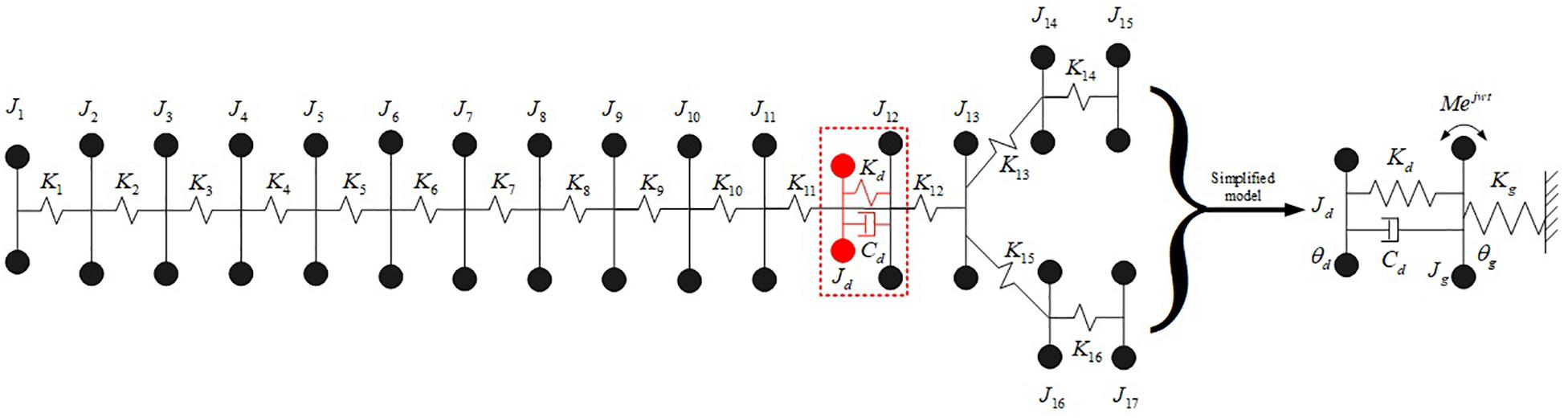
Figure 1. System equivalent model with torsional vibration absorber.
Based on the equivalent model, the dynamic equation of the powertrain system can be obtained as shown in Equation (1). When and Cd = 0, the equation is the differential equation of the currently common automobile powertrain system.
The periodic fluctuating torque of the engine is the main excitation source of the powertrain system, including the torque Tg produced by the cylinder gas pressure and the inertial torque Ti of the rotating parts. The formulas of the output torque Ttotal of the engine are as follows (Robert, 2007).
The equivalent damping torque of the powertrain system is formulated as follows.
To solve the inherent characteristics of the powertrain system, the torsional differential equation of the un-damped free vibration of the powertrain system is obtained as follow.
The natural frequencies and sensitivity analysis of the powertrain system are obtained as shown in Table 1.
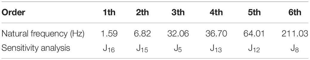
Table 1. Natural frequency value and sensitivity analysis.
A four-cylinder four-stroke engine is adopted here. The second-order main harmonic is the main excitation of the engine and the main factor that causes the torsional vibration of the powertrain system. From the following formula, the frequency of the second-order main harmonic of engine excitation can be obtained.
Here r = 2 is set. It is well known that the rotating velocity range of an automobile engine is generally between 1500 and 6000 rpm. Formula 9 and Table 1 show that the rotating velocity corresponding to the 5th order natural frequency of the powertrain system is 1920 rpm, which is within the normal working rotating velocity range of the engine. When the engine approaches this rotating velocity, resonance will occur, which will affect the ride comfort of the vehicle, and may cause fatigue damage to the system components. The emphasis of this paper is to effectively suppress the torsional vibration of the powertrain system near to the rotating velocity of 1920 rpm by installing a torsional vibration absorber.
According to the sensitivity analysis of the moment of inertia to the eigenvalues of the system, it can be seen that the moment of inertia of the J12 inertia disk is most sensitive to the 5th-order natural frequency of the system, which also determines the installation position of the torsional vibration absorber as shown in Figure 1.
To analyze the vibration reduction mechanism of the torsional vibration absorber, a two-degree-of-freedom simplified torsional vibration model is obtained as shown on the right side of Figure 1 by taking the powertrain system as a whole. The dynamic equation of the two-degree-of-freedom torsional vibration model is as follows.
Take the excitation torque as M(t) = Mejwt. Assume that the solution to equation (10) is as follows.
Then the amplitude of the main system can be obtained.
Here we introduce the following parameter variables.
The amplitude multiplier of the main system Rg can be expressed as.
As a typical two-degree-of-freedom system, when the absorber’s damping ratio σ is changed, the system’s amplitude radio curves with different damping ratios can be obtained. When the natural frequency ratio of torsional vibration absorber to the main system γ = 1 is set, the passive control curve in the right picture of Figure 2 can be obtained. The following results can be obtained by introducing into Equation (13).
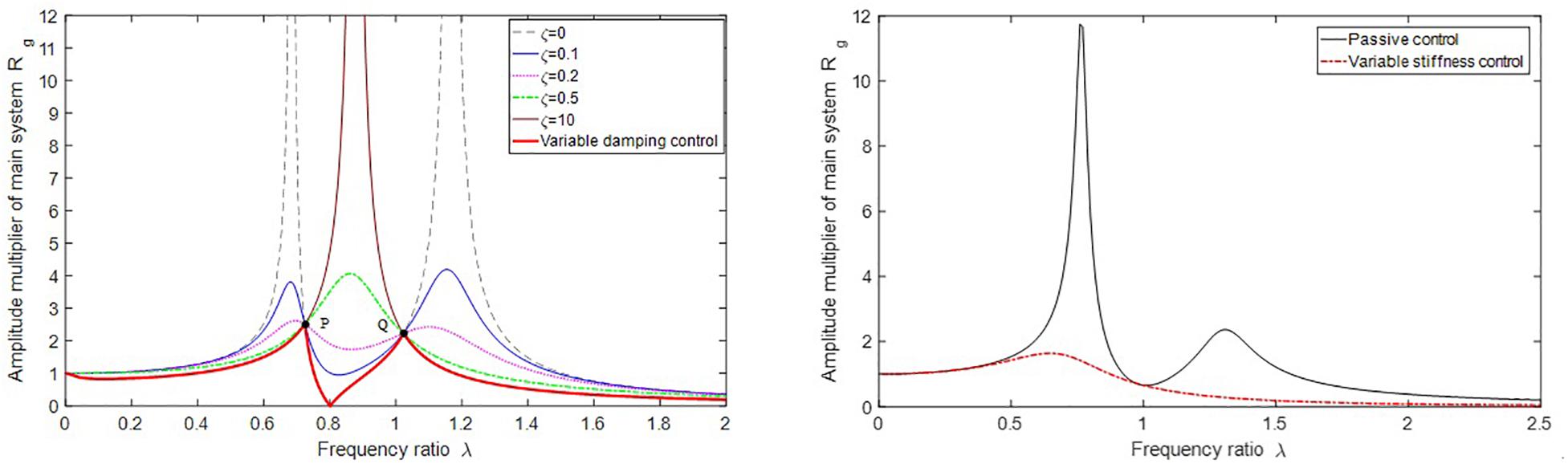
Figure 2. Effect of damping and stiffness parameter control of torsional vibration absorber on the powertrain system.
Where f is the ratio of the excitation frequency to the natural frequency of the torsional vibration absorber. When f=1 is set, it means that the natural frequency of the torsional vibration absorber changes with the change of the excitation frequency. Hence, the variable stiffness control curve in the right picture of Figure 2 is obtained. It can be seen that the vibration response of the main system can be effectively improved by real-time control of the damping and stiffness of the torsional vibration absorber.
Here the ratio is obtained and the equivalent model parameters of the powertrain systerm are shown in Table 2. The moment of inertia J_d of the torsional absorber can be selected. Since the required control frequency of the powertrain system is f5 = 64Hz, the stiffness adjustment range of the MR-VSDTVB needs to cover the stiffness value corresponding to the frequency f5.
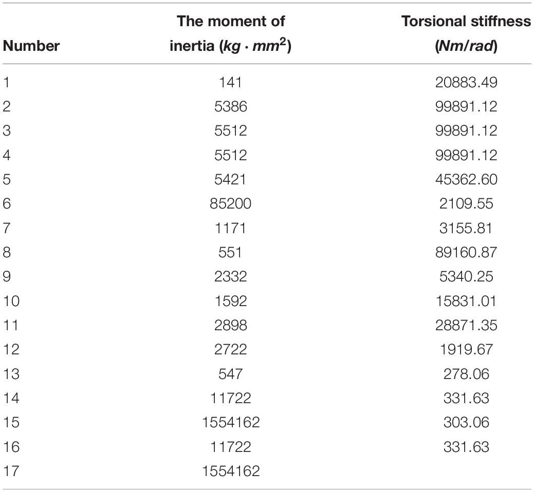
Table 2. Equivalent model parameters of the powertrain system.
Sections 2 verifies that the variable stiffness and damping torsional vibration absorber can effectively suppress the torsional vibration of the main system within a certain frequency range, through changing the stiffness and damping values in real time. A magneto-rheological variable stiffness and damping torsional vibration absorber (MR-VSDTVB) was designed and fabricated to realize the research on torsional vibration control of the powertrain system.
Figures 3A,B show that the MR-VSDTVB consists of a rotating variable damping element and a rotating variable stiffness element in parallel. The core component of the rotating variable damping element is a disk MR damper. The rotating variable stiffness element consists of two sets of variable stiffness components which are symmetrically installed in the variable stiffness disc groove. Each set of variable stiffness components involes a linear MR damper and two arc springs with different stiffness, which are placed at both ends of the damper.

Figure 3. Description of the MR-VSDTVB. (A) Working principle. (B) Structural and prototype. (C-a) Actual model. (C-b) Equivalent model. (C) The MR-VSDTVB model.
When the primary flywheel and the sliders of the MR-VSDTVB rotate under the action of the external torque, the primary and secondary flywheels of the MR-VSDTVB rotate relatively to each other accordingly. In addition, the torque between them is composed of the damping torque generated by variable damping element and the stiffness generated by variable stiffness element. The semi-active adjustment of the damping torque of variable damping element can be achieved by changing the current applied to the disk MR damper. The stiffness torque generated by variable stiffness element is composed of the damping forces generated by linear MR dampers, and the spring forces generated by compression deformation of the springs Kd2 and Kd1. The damping forces provided by the linear MR dampers can be adjusted by changing the currents applied to coils of the dampers, and compressive deformation of the springs Kd2 and Kd1 can be changed, respectively, without changing the total deformation amount. Finally, the purpose of indirectly adjusting the stiffness of variable stiffness element is achieved. The details of the MR-VSDTVB are specified in paper (Wang, 2019), which will not be described here. The MR-VSDTVB model can be obtained from the working principle and structure of the MR-VSDTVB as shown in Figure 3C.
Figure 3C-a shows that MR damper Cs is connected in parallel with arc spring Kd2, then connected in series with arc spring Kd1 to form equivalent variable stiffness element, and finally connected in parallel with MR damper Cd to form the MR-VSDTVB. The equations of motion for the system shown in Figure 3C-a are as follows.
Let the excitation torsion torque M(t) = M0eiwt,θ0 = 0, and it can be obtained from the upper equations.
The corresponding transfer function of the equivalent model shown in Figure 3C-b is
Comparing Equation (17) with Equation (16), the equivalent stiffness and damping coefficients are as follows.
Where . Equations (18) and (19) indicate that equivalent stiffness Kd is only related to Cs, and is influenced by Cs and Cd. If Cs = 0, the nKd = Kd1⋅Kd2/(Kd1 + Kd2), . If Cs = ∞, then Kd = Kd1, . Hence, adjusting the damping coefficient Cs can play an equivalent role in regulating the stiffness of the system. Although adjusting the damping coefficients Cs and Cd can adjust the equivalent damping of the system, the effect of damping Cd on the equivalent damping of the system is much greater than that of damping Cs. Consequently, two MR dampers Cs and Cd with controllable damping coefficients can be used to adjust the equivalent damping and stiffness of the system approximately independently.
Considering that the variable stiffness element and variable damping element of MR-VSDTVB are arranged in parallel, the test scheme adopted here is to test the mechanical characteristics of the two elements separately. The performances of MR-VSDTVB under different excitation frequencies, different excitation angular amplitudes, and different currents were tested on the MTS test bench. The stiffness and damping mechanical properties of MR-VSDTVB were tested, respectively, and the test curves of Figures 4A,B are selected as representative for display.
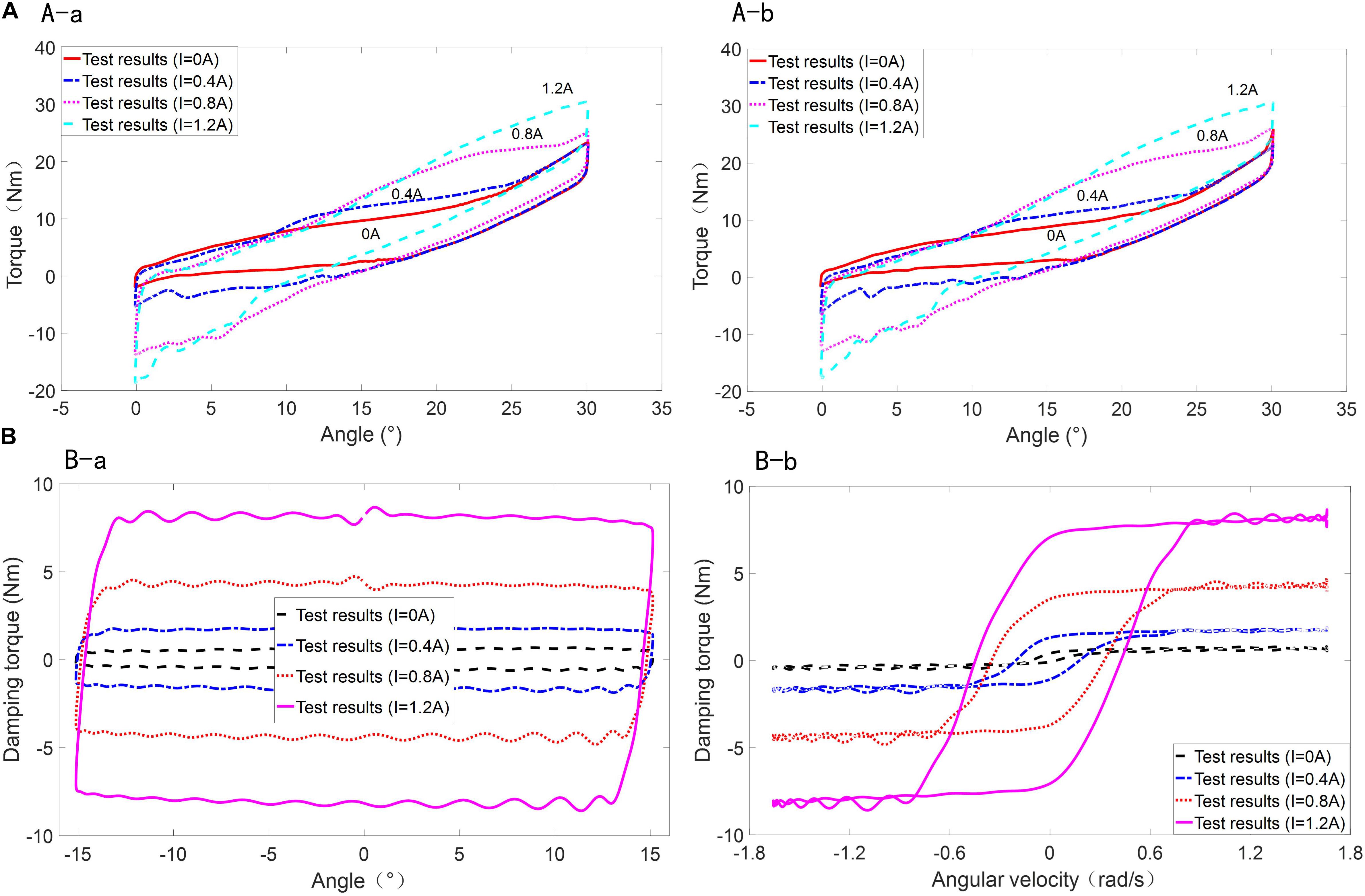
Figure 4. The test curve of MR-VSDTVB under different current. (A-a) Rotating angle-torque (0.2 Hz). (A-b) Rotating angle-torque (0.6 Hz). (A) Variable stiffness element for MR-VSDTVB. (B-a) Rotating angle-torque (1.0 Hz). (B-b) Rotating velocity-torque (1.0 Hz). (B) Variable damping element for MR-VSDTVB.
Figure 4A shows that the torque required by MR-VSDTVB at the same rotation angle increases with the increase of current, which also indicates that the stiffness of MR-VSDTVB increases gradually.
It can be seen from Figure 4B-a that under the same amplitude and frequency conditions, the damping force of MR-VSDTVB also increases continuously with the increment of current, so is the envelope of the power diagram. Consequently, the energy consumption of MR-VSDTVB increases with the increase of current. From Figure 4B-b, it is known that the damping torque of MR-VSDTVB increases with the increment of the current at the same rotation velocity.
Figures 4A,B show that the stiffness force and damping force of MR-VSDTVB have a controllable characteristic. The semi-active control of the stiffness and damping of the MR-VSDTVB can be achieved indirectly by controlling the coil currents.
According to the characteristic analysis of the test curves of the MR-VSDTVB’s variable stiffness element and variable damping element, it is found that the polynomial model is suitable for the modeling of the variable stiffness element Td, and the hyperbolic tangent model is suitable for the modeling of the variable damping element Tc. The mathematical expressions of the hyperbolic tangent model and polynomial model are as follows.
Where c = b1I2 + b2I + b3, k = b4I2 + b5I + b6, α = b7I + b8, β = b9I2 + b10I + b11, δ = b12I2 + b13I + b14, ai = diI3 + eiI2 + giI + hi and I is the applied current input.
By fitting the test data with the above mathematical models, the parameters of the mathematical models are obtained as shown in Table 3.
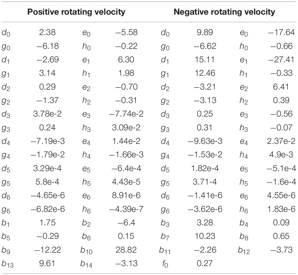
Table 3. Parameters of the MR- VSDTVB model.
Equations (20) and (21) may be expressed as.
For functions (22) and (23), the optimization method, such as the Golden Section method, can be used to obtain the required control currents of the variable stiffness element and the variable damping element (Aliases are the inverse models), respectively. In the actual system test, the look-up table method can be used to ensure the response speed of the real-time control.
The control currents of the variable damping element Ic and the variable stiffness element Id are used for semi-active control of the MR-VSDTVB’s damping torque and stiffness torque, respectively.
The polynomial model of the variable stiffness element and hyperbolic tangent model of the variable damping element are compared with the test data of MR-VSDTVB as shown in Figures 5A,B.
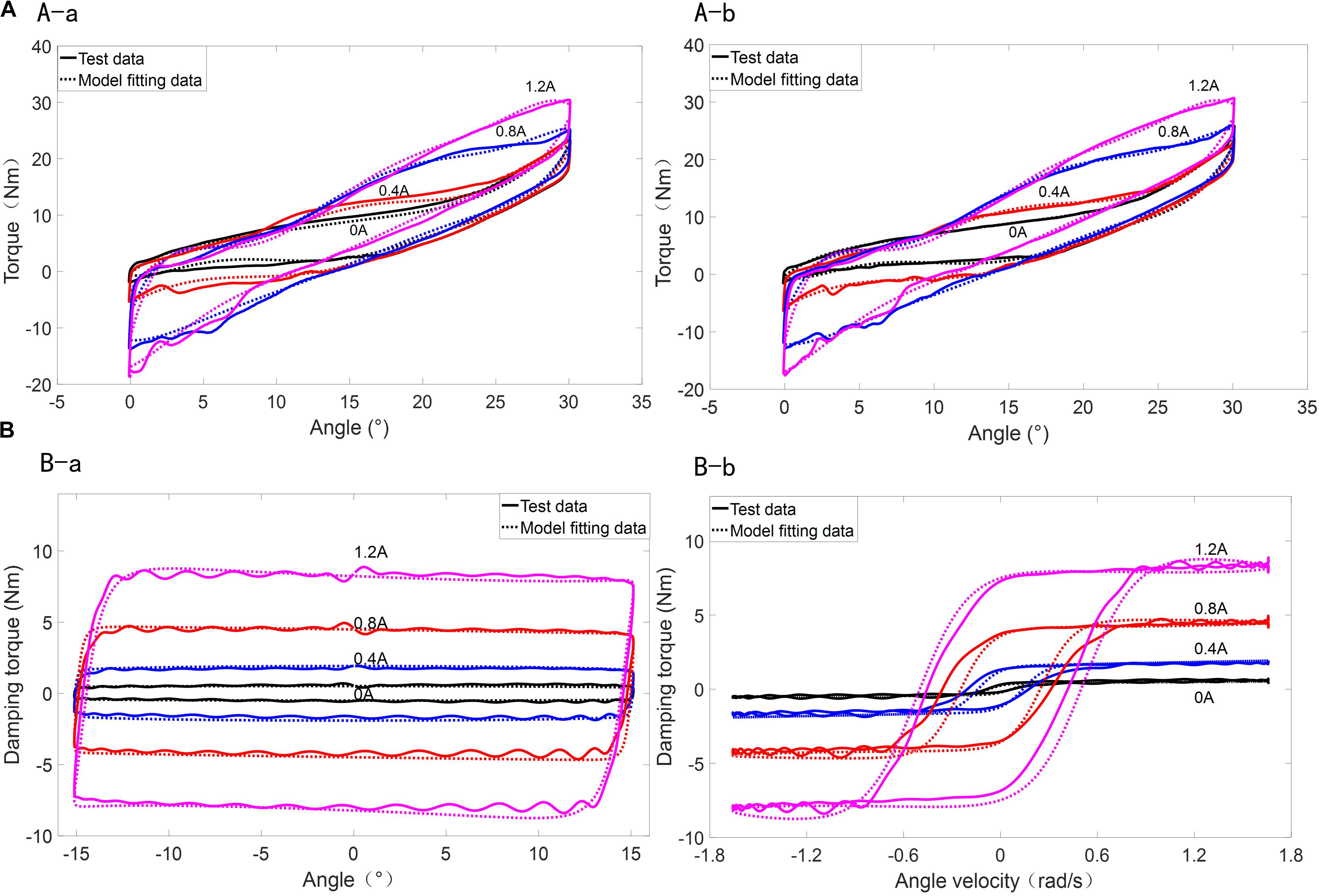
Figure 5. Model Prediction of the MR-VSDTVB. (A-a) Rotating angle-torque (0.2 Hz). (A-b) Rotating angle-torque (0.6 Hz). (A) Model prediction of variable stiffness element for the MR-VSDTVB. (B-a) Rotating angle-torque (1.0 Hz). (B-b) Rotating velocity-torque (1.0 Hz). (B) Model prediction of variable damping element for the MR-VSDTVB.
Figures 5A,B show that the mathematical models used here can approximate the test data well and describe the hysteresis characteristics of MR-VSDTVB under the illustrated frequency and amplitude as well as different currents. Similar results are also found at other excitation frequencies and amplitudes. Figure 5 also shows that when the torque of the variable stiffness element of MR-VSDTVB is known at any relative angle, the corresponding stiffness can be obtained, which reveals the stiffness and the torque are both controllable and available in real time.
To effectively suppress the torsional vibration of the powertrain system, a human-simulated intelligent controller (HSIC) is designed. The original HSIC algorithm, which was first proposed by Zhou and Bai (1983) in 1983, has become a fundamental and systematic method used in resolving some general industrial control problems for the last 30 years. In recent years, the HSIC theory has been further advanced through combing with the schema theory of modern cognitive science. After many years of research, HSIC theory based on sensory-motor intelligent schema (SMIS) has come into being (Li et al., 2004). The theory provides a more effective and systematic method in resolving some complex control problems.
By setting the engine cylinder pressure in the time domain, the ideal rotating velocity of the main reducer’s shaft is obtained from the design of the test plan. In the numerical simulation process, the ideal rotating velocity of the main reducer’s shaft is obtained through the transmission ratio of the powertrain system. The input shaft of the main reducer actual rotating velocity-time relationship and ideal rotating velocity-time relationship are shown in Figure 6A. In the process of acceleration, the difference between the actual rotating velocity curve and the ideal rotating velocity curve are selected as the rotating velocity fluctuation error. The photograph on the right side of Figure 6A is the amplitude-frequency curve, which is obtained by Fourier transforming of the rotating velocity curve of the main reducer’s input shaft.
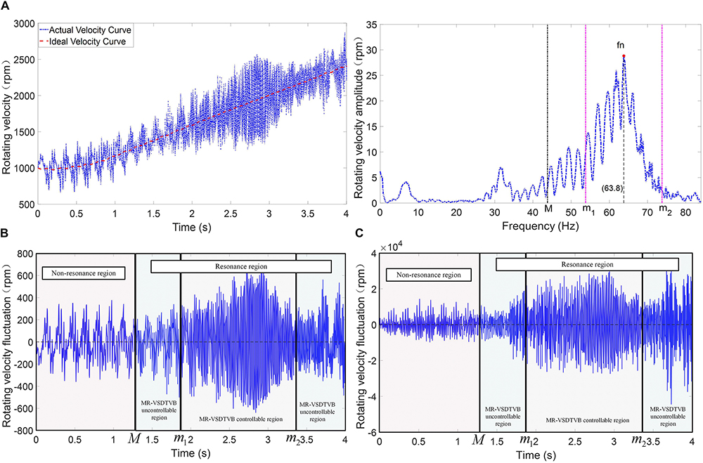
Figure 6. Control input signal of the powertrain system. (A) Rotating velocity-time relationship and amplitude-frequency relationship. (B) Rotating velocity fluctuation error. (C) Rotating acceleration fluctuation error.
The system excitation main frequency fe, the rotating velocity fluctuation error and the rotating acceleration fluctuation error (error e and error derivative ) of the main reducer’s input shaft are selected as input signals as shown in Figure 6. The excitation frequency fe is used to judge the state of the system. The resonance frequency fn of the powertrain system, which is shown in the photograph on the right side of Figure 6A, is basically consistent with the 5th natural frequency of the powertrain system shown in Table 1. The photograph on the right side of Figure 6A shows that the region near the resonance frequency fn is set as the resonance region, and the remaining region is set as non-resonant region. The second section shows that the torsional vibration of the system in the resonance region can be suppressed to a large extent by adjusting the MR-VSDTVB stiffness to make the natural frequency consistent with the excitation frequency of the powertrain system. Because the natural frequency adjustment of the MR-VSDTVB does not cover the entire resonance region in the design and test of the MR-VSDTVB, the resonance region is divided into the MR-VSDTVB controllable region and the MR-VSDTVB uncontrollable region in the actual control as shown in Figure 6. The controller divides the state characteristic information space of the system into the following three regions according to Figure 6.
Where fn represents the 5th natural frequency of the powertrain system, which is approximately 64 Hz. M denotes the range of the resonance region. M = 20 is adopted according to the description of Figure 6. [m1m2] represents the operating frequency range of MR-VSDTVB.
For the non-resonant region as shown in Figures 7A,B, four thresholds e1, e2, e3 and e4 are set to divide the rotating velocity fluctuation error curve into , , , , and regions according to fluctuation error value. Similarly, four thresholds de1, de2, de3 and de4 are set to divide the rotating acceleration fluctuation error curve into , , , and regions. Different control parameters and control strategies are selected to control the torsional vibration of the system under different combinations of rotating velocity fluctuation region and rotating acceleration fluctuation region.
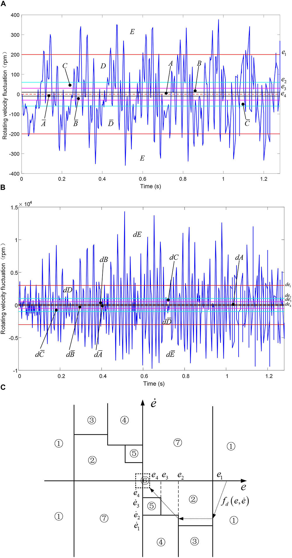
Figure 7. Error Classification of HSIC. (A) Rotating velocity fluctuation error in non-resonant region. (B) Rotating acceleration fluctuation error in non-resonant region. (C) Feature model of HSIC.
Feature model of HSIC in non-resonant region is shown in Figure 7C. The abscissa is represented by the rotating velocity fluctuatione, and the ordinate is represented by the rotating acceleration fluctuatione. Figure 7C shows that the whole region is transformed into seven characteristic modes, and the dotted lines indicate the desired phase trajectory .
The ideal objective for controlling the error trajectory is to make the rotating velocity fluctuation error and the rotating acceleration fluctuation error both reach zero, and the actual rotating velocity follows the ideal rotating velocity of the shaft of the main reducer as shown in Figure 6A. When there are errors in the system response, the error trajectory is adjusted along the phase trajectory curve in Figure 7C from the larger error regions to the smaller error regions, and finally the desired minimum errors are expected.
A sensed schema group can be formulated by:
The characteristic primitive set is chosen according to the states of the powertrain system, which can be expressed as follow.
in which q6:|e|≥e3, q7:|e|≥e4, , , , .
The sensed characteristic model can be written as follows, and the characteristic modes are represented by ϕi.
The motion schema can be described as follow.
The associated schema can be expressed as follow.
where
Figure 8A shows the operation process of the HSIC control scheme of MR-VSDTVB and the relationship between different schemes. According to the measured rotating velocity of the shaft of the main reducer, the corresponding excitation frequency fe is obtained by Equation (9). When the excitation frequency is in the resonance region, it is necessary to further distinguish whether the excitation frequency is in the MR-VSDTVB controllable region or MR-VSDTVB uncontrollable region, and then the required MR-VSDTVB stiffness value Kd and damping torque value Tc can be obtained through corresponding control modes. When the excitation frequency fe is in the non-resonant region, the characteristic mode of the current system response is judged by Figure 7, and then the required MR-VSDTVB stiffness value Kd and damping torque value Tc can be obtained according to the corresponding relationship between the characteristic modes and the control modes. Further, the control current Ic applied to the variable damping element and Id applied to the variable stiffness element can be obtained from the inverse model Equation (19) and (20) of the MR-VSDTVB. Finally, the obtained control currents Id and Ic are, respectively, applied to the variable stiffness element and the variable damping element of the MR-VSDTVB to realize the semi-active control of the MR-VSDTVB. Figure 8B shows the block diagram of the semi-active HSIC powertrain system obtained from Figure 8A.
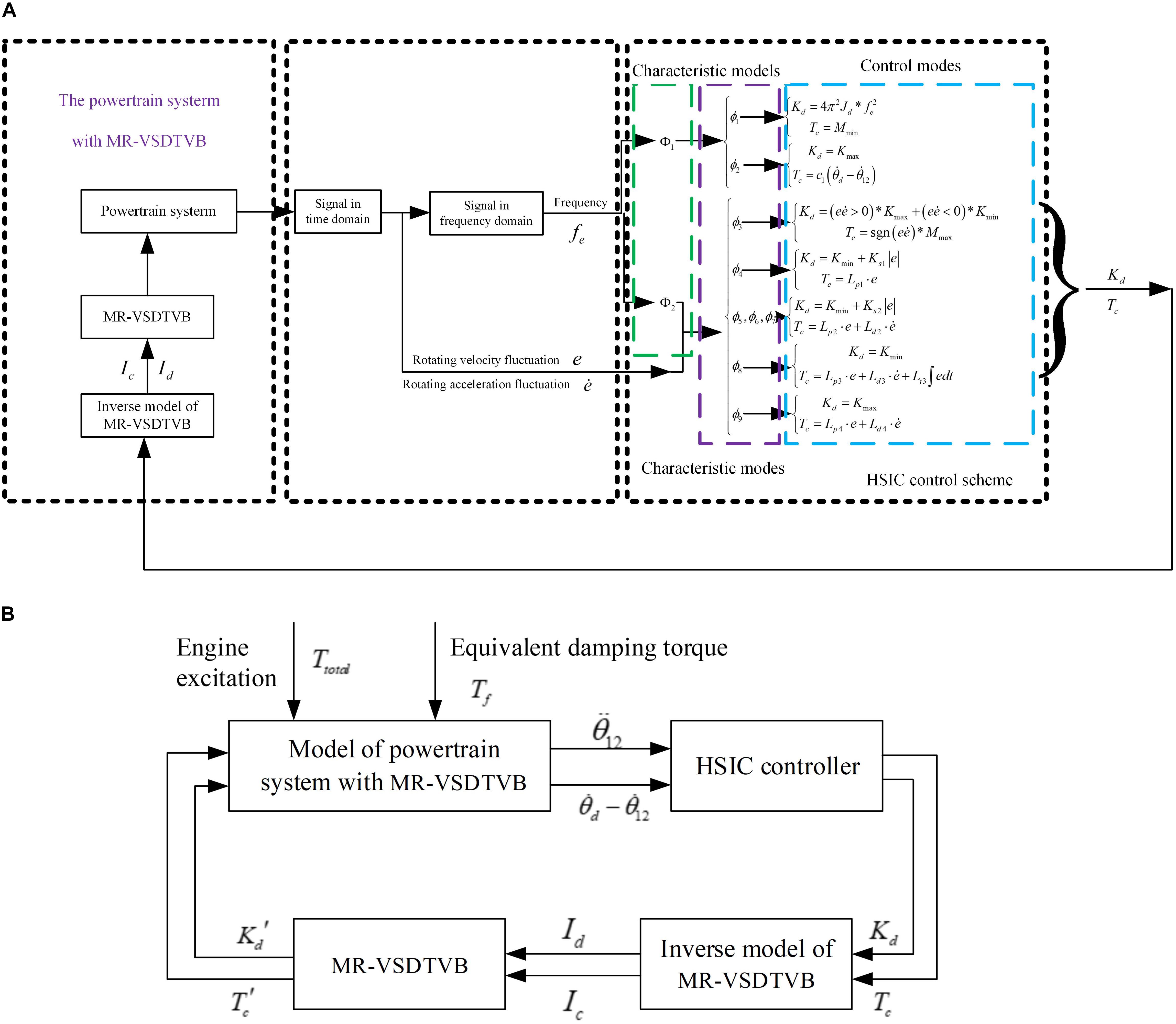
Figure 8. Semi-active HSIC diagram for the powertrain system with MR-VSDTVB. (A) HSIC control scheme for MR-VSDTVB. (B) Block diagram of the semi-active HSIC powertrain system.
Due to the limitation of the stiffness adjustment range of the MR-VSDTVB and the fact that the damping element of the MR-VSDTVB is an energy dissipating element, the control output is adjusted as follows.
Where and TMR represent the actual output stiffness value and damping torque value of the MR-VSDTVB Kmax and Kmin are the maximum and minimum stiffness values that the MR-VSDTVB can provide, respectively indicate the rotating velocity of the MR-VSDTVB and the main reducer’s shaft. Tmax and Tmin are the maximum and minimum damping torque values that the MR-VSDTVB can provide.
To verify the effectiveness of the proposed semi-active HSIC controller, a numerical simulation system based on MATLAB/Simulink is established.
In this paper, the torsional vibration response of the main reducer in the powertrain system is taken as the control objective, and the RMS value and the decreasing index of the torsional vibration response are taken as the criteria for evaluating the control effectiveness (Wang et al., 2015). The numerical simulation condition is the acceleration process of the automobile engine from idle condition (900 rpm) to 2500 rpm.
The torsional vibration responses of the input shaft of the main reducer in the powertrain system are compared in three cases, which are without MR-VSDTVB, MR-VSDTVB without control and MR-VSDTVB with control. Figure 9 shows the numerical simulation results.
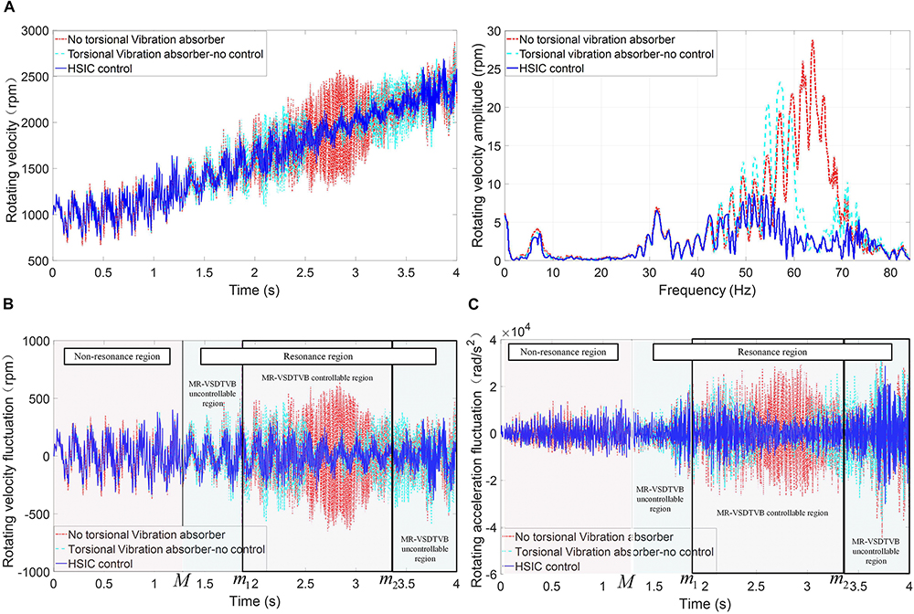
Figure 9. Contrast of input shaft response of the main reducer in the powertrain system. (A) Rotating velocity-time relationship and amplitude-frequency relationship. (B) The rotating velocity fluctuate. (C) The rotating acceleration fluctuate.
The simulation results show that the amplitude of the rotating velocity fluctuation and the rotating acceleration responses can be reduced by installing MR-VSDTVB on the input shaft of the main reducer, and the semi-active HSIC control of MR-VSDTVB can suppress the torsional vibration of the powertrain system to a large extent.
To further verify the control effect of HSIC, the on-off damping control and the on-off stiffness control are adopted for comparison. The expressions of the on-off damping control and the on-off stiffness control are as follows.
The output responses of the powertrain system under different controls are shown in Figure 10. Figure 10 demonstrates that the torsional vibration control effect of HSIC is obviously better than the on-off damping control and the on-off stiffness-damping control, and HSIC can effectively suppress the rotating velocity fluctuation amplitude and rotating acceleration amplitude of the main reducer’s input shaft, when the excitation frequency approaches the resonance frequency. The rotating acceleration curve of the on-off stiffness control contains some abrupt amplitudes, which are mainly caused by the step change of stiffness in the control process.
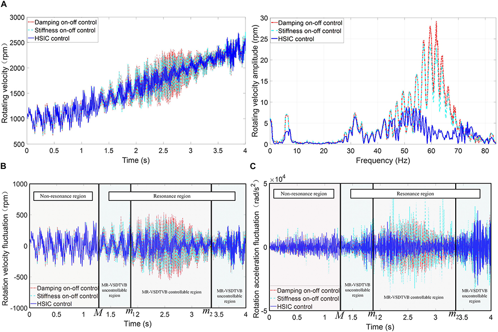
Figure 10. Contrast of input shaft response of the main reducer in the powertrain system with different controls. (A) Rotating velocity-time relationship and amplitude-frequency relationship. (B) The rotating velocity fluctuate. (C) The rotating acceleration fluctuate.
The stiffness change curve and damping torque change curve in the HSIC control process are shown in Figure 11, from which the control output under different system responses can be observed. The root mean square values of system responses under different controls in different regions are shown in Figure 12, respectively. Figure 12 shows that HSIC in resonant and MR-VSDTVB controllable region has the excellent torsional vibration control effect, which is obviously better than that in MR-VSDTVB uncontrollable region and non-resonance region. It also shows that a better vibration control effect can be achieved, by adopting the variable stiffness control strategy to make the natural frequency of MR-VSDTVB consistent with the excitation frequency of the system in the resonance region (the RMS values of rotating velocity can be reduced to 36% at most.). The HSIC control in the non-resonance region can also suppress the torsional vibration of the system to a certain degree, and the RMS values of the rotating velocity and the rotating acceleration can be reduced to 90 and 74% at most, respectively.
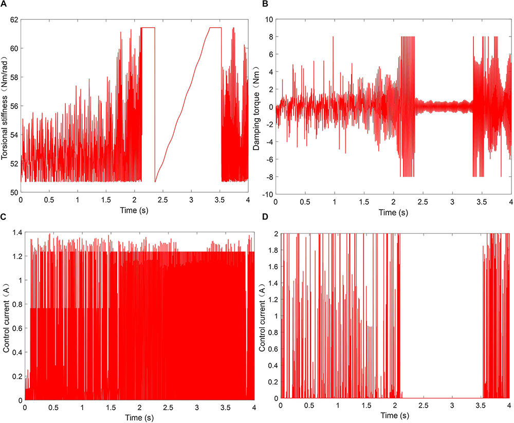
Figure 11. Variation of parameters in the simulation process. (A) The stiffness change. (B) The damping torque change. (C) Current of variable stiffness part. (D) Current of variable damping part.
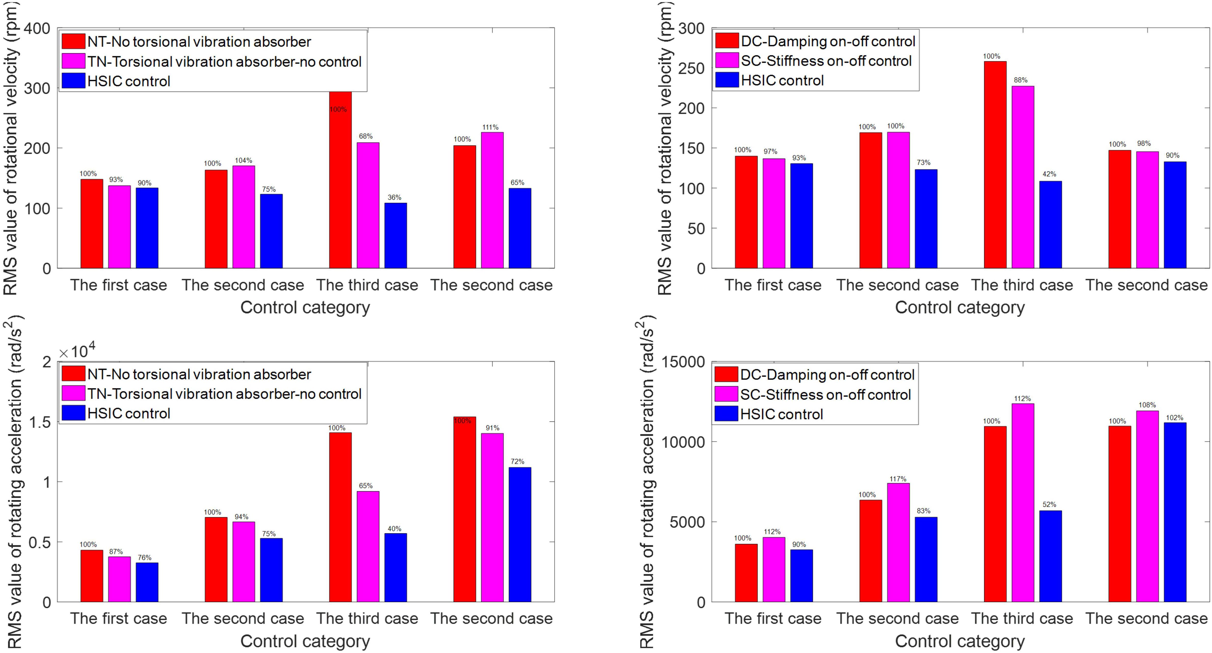
Figure 12. Root mean square value of vibration response in different regions. The first case – Non-resonant region; the second case – Resonant and MR-VSDTVB uncontrollable region; The third case – Resonant and MR-VSDTVB controllable region.
Based on the above simulation results, the overall peak and RMS values of rotating velocity fluctuation and rotating acceleration of the main reducer’s input shaft under different controls are calculated as shown in Figure 13. In view of the overall effect of torsional vibration suppression, the peak and RMS values of rotating acceleration can be reduced by 55.18 and 32.3%, respectively, when the HSIC control is applied to MR-VSDTVB. Even the on-off stiffness control and the on-off damping control can effectively reduce the peak and RMS values of rotating velocity to a lower level (by 20.66 and 30.55% at most, respectively).
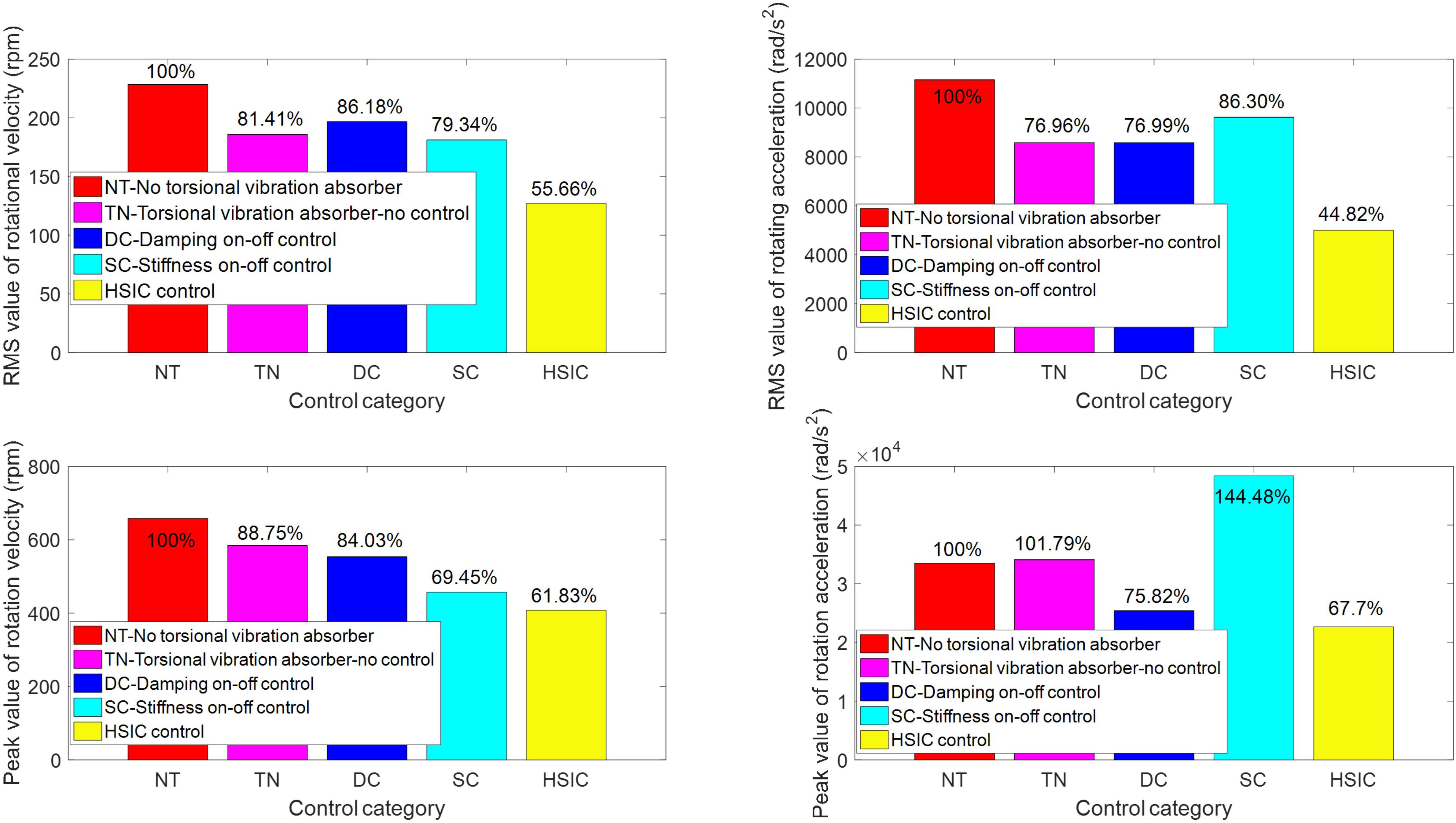
Figure 13. Peak value and root mean square value of vibration response.
In this study, a MR-VSDTVB and a HSIC controller are proposed to suppress the torsional vibration response of the powertrain system. The details can be concluded as follows.
(a) A MR-VSDTVB is designed, fabricated and tested. Based on the test results, the models of the variable stiffness element and variable damping element of the MR-VSDTVB are proposed.
(b) The multi-degree-of-freedom dynamic model of the powertrain system is established, and the installation position and adjustment range of MR-VSDTVB are determined by system analysis.
(c) A HSIC controller is proposed to control the MR-VSDTVB to suppress the torsional vibration response of the powertrain system.
(d) The performance of the proposed control strategy is evaluated under the acceleration process of the engine. The numerical simulation results indicate that the semi-active control of MR-VSDTVB with the HSIC controller has a better control effect than other controllers. Compared with the case without MR-VSDTVB, the RMS reduction rates of e and in the powertrain system with MR-VSDTVB are 44.34 and 55.18%, respectively. At the same time, the peak values of e and in the powertrain system with MR-VSDTVB are reduced by 38.17 and 32.30%, respectively, compared with the case without MR-VSDTVB. The torsional vibration of the powertrain system can be suppressed in a wide frequency band by installing the MR-VSDTVB at the specified position of the powertrain system.
The raw data supporting the conclusions of this article will be made available by the authors, without undue reservation, to any qualified researcher.
XD contributed to content layout, and the conception and verification of the whole manuscript. WL was responsible for writing the manuscript and the numerical simulation. CP contributed to auxiliary parts of the simulation and data collection. JX was responsible for verifying the manuscript. XW was responsible for designing and providing technical support for the torsional vibration absorber used in the manuscript. JY contributed to the conception and discussion of the overall framework of the manuscript, and helped to determine and discuss the revision scheme for the manuscript. YZ participated in drawing some of the figures in the manuscript and the modification of the manuscript.
The authors disclosed receipt of the following financial support for the research, authorship, and/or publication of this article: This work was financially supported by the National Natural Science Foundation of People’s Republic of China (Project No. 51675063), this research is also supported by graduate Research and Innovation Foundation of Chongqing, China (Grant No. CYB17023). These supports are gratefully acknowledged.
The authors declare that the research was conducted in the absence of any commercial or financial relationships that could be construed as a potential conflict of interest.
Davis, C. L., Lesieutre, G. A., Dosch, J. J., and Davis, L. P. (1997). A tunable electrically shunted piezoceramic vibration absorber. Proc. -Int. Soc. Opt. Eng. 3045, 51–59.
Deng, H. X., and Gong, X. L. (2007). Adaptive tuned vibration absorber based on magnetorheological elastomer. J. Intell. Mater. Syst. Struc. 8, 1205–1210.
Fu, J., Li, P., Liao, G., Lai, J., and Yu, M. (2016). Development and dynamic characterization of a mixed mode magnetorheological elastomer isolator. IEEE Trans. Mag. 53, 1–4.
Gao, P., Xiang, C., Liu, H., and Zhou, H. (2018). Reducing variable frequency vibrations in a powertrain system with an adaptive tuned vibration absorber group. J. Sound Vib. 425, 82–101.
Harris, B. J., Sun, S. S., and Li, W. H. (2017). Improving stability and curving passing performance for railway vehicles with a variable stiffness MRF rubber joint. Smart Mater. Struc. 26, 035–055.
Hoang, N. (2011). An Adaptive Tunable Vibration Absorber Using Magnetorheological Elastomers for Vibration Control of Vehicle Powertrains. Sydney: University of Technology Sydney, 1–20.
Huang, H., Sun, S. S., Chen, S. M., and Li, W. H. (2019). Numerical and experimental studies on a new variable stiffness and damping magnetorheological fluid damper. J. Intell. Mater. Syst. Struc. 30, 1639–1652.
Johann, M. G., Hermann, P., and Karsten, S. (2014). Innovative torsional vibration reduction devices - vehicle-related design and component strength analysis. SAE Int. J. Passeng. Cars Mech. Syst. 7, 1392–1403.
Kang, Q., Wu, Y. D., Deng, J. H., and He, S. D. (2014). Study on the application of torsional vibration damper for the drivetrain torsional vibration of a FR car. Manuf. Autom. 36, 92–94.
Li, Z. S., Zhang, H., and Wen, Y. L. (2004). “Human simulated intelligent control based on sensory-motor intelligent schemas,” in Proceedings of the 5th World Congress on Intelligent Control and Automation, Hangzhou: IEEE 3, 2423–2427.
Nagaya, K., Kurusu, A., Ikai, S., and Shitani, Y. (1999). Vibration control of a structure by using a tunable absorber and an optimal vibration absorber under autotuning control. J. Sound Vib. 228, 773–792.
Qian, L. J., Xin, F. L., Bai, X. X., and Wereley, N. (2017). M. State observation–based control algorithm for dynamic vibration absorbing systems featuring magnetorheological elastomers: Principle and analysis. J. Intell. Mater. Syst. Struc. 28, 2539–2556.
Qing-Hua, Z., Zhi-Yong, C., Wen-Ku, S., Qing-Hua, Z., and Zhi-Yong, C. (2015). Torsional vibration semi-active control of drivetrain based on magneto-rheological fluid dual mass flywheel. Math. Probl. Eng. 2015, 1–17.
Sun, S. S., Yang, J., and Li, W. H. (2016). Development of an isolator working with magnetorheological elastomers and fluids. Mech. Syst Signal Process. 83, 371–384.
Wang, D., Yan, B., Wang, D. L., and Wang, Y. W. (2015). Noise control method of interior booming induced by torsional vibration of driveline system. Noise Vib. Control. 35, 73–76.
Wang, X. H. (2019). Principle and Experiment of Variable Stiffness Damping of Magnetorheological Torsional Damper in Power Driveline. Chongqing: Chongqing University, 21–49.
Wang, Y., and Jing, X. J. (2018). Nonlinear stiffness and dynamical response characteristics of an asymmetric X-shaped structure. Mecha. Syst. Signal Process. 125, 142–169.
Williams, K., Chiu, G., and Bernhard, R. (2002). Adaptive-passive absorbers using shape-memory alloys. J. Sound Vib. 249, 835–848.
Xu, Z. B. (2010). Study on Adaptive Tuned Vibration Absorbing Technology. Hefei: University of Science and Technology of China, 1–10.
Ye, S. C. (2012). Passive and Semi-Active Torsional Vibration Control. Tuscaloosa: The University of Alabama, 1–10.
Yu, J. Q., Dong, X. M., Zhang, Z. L., and Chen, P. G. (2018). A novel scissor-type magnetorheological seat suspension system with self-sustainability. J.Intell. Mater. Sys. Struc. 30:1045389X1775425.
Zhang, D. (2015). Optimizing the Parameters of Dynamic Vibration Absorber and Researching on the Active Control. Xi’an: Changan University, 1–20.
Zhang, X. Z., and Li, W. H. (2009). Adaptive tuned dynamic vibration absorbers working with MR elastomers. Smart Struct. Syst. 5, 517–529.
Zhou, Q. J., and Bai, J. K. (1983). “An intelligent controller of novel design,” in Proceedings of Multi-National InstruCion Conference, Part. 1, (Shanghai: Science Technology Literature Press), 137–149.
J1 The moment of inertia at the free end of the engine, kg⋅mm2
J2,J3,J4,J5 The 1∼4 moments of inertia of cylinder crank connecting rod group on the engine,kg⋅mm2
J6 The moment of inertia of the flywheel and the front of the clutch,kg⋅mm2
J7 The moment of inertia of the driven disk of the clutch and the front part of the input shaft of the transmission,kg⋅mm2
J8 The moment of inertia of the rear end of the transmission input shaft and the pair of constant meshing gears,kg⋅mm2
J9 The moment of inertia of the main and follower gear pairs in each gear position and the front section of the output shaft,kg⋅mm2
J10 The moment of inertia of the rear section of the output shaft and the front section of the transmission shaft,kg⋅mm2
J11 The moment of inertia of the middle section of the output shaft,kg⋅mm2
J12 The moment of inertia of the rear section of the drive shaft and the main reducer’s active components, kg⋅mm2
J13 The moment of inertia of the follower of the main reducer, the differential and the front half of the shaft,kg⋅mm2
J14,J16 The moment of inertia of left axle and left wheels, right axle, and right wheels, respectively,kg⋅mm2
J15,J17 Half of the translational mass equivalent moment of inertia of the vehicle body, respectively,kg⋅mm2
K1,K5 The torsional stiffness between the free end of the engine and the crankshaft, between the flywheel and the crankshaft of the engine,Nm/rad
K2,K3,K4 The torsional stiffness of cylinder crank connecting rod group on the engine, respectively,Nm/rad
K6 The torsional stiffness of the clutch,Nm/rad
K7,K8,K9 The input shaft torsional stiffness, intermediate shaft torsional stiffness and output shaft torsional stiffness of transmission,Nm/rad
K10,K11 The torsional stiffness of the front and middle segments of the transmission shaft,Nm/rad
K12 The torsional stiffness of the input shaft of the main reducer,Nm/rad
K13,K15 The torsional stiffness of the left and right axes, respectively, Nm/rad
K14,K16The equivalent torsional stiffness of the left and right wheels, Nm/rad
PA The single cylinder gas pressure, N/m2;
Ag The piston area of the cylinder,m2;
R,l The crankshaft radius and connecting rod length, m
ω The crankshaft angular velocity,rad/s
mB The piston equivalent mass, kg
Fw The air resistance, N
Fr The rolling resistance in motion, N
rwheel The wheel radius, m
i0 The transmission ratio
CD The air drag coefficient
A The windward area of the vehicle,m2
V The driving speed of the vehicle, m/s
χ The rolling damping coefficient between wheel and road
mv The vehicle mass, kg
g The gravity acceleration, m/s2
Tg The torque produced by the cylinder gas pressure, Nm
Ti The inertial torque of the rotating parts, Nm
Ttotal The output torque of the engine, Nm
r The order of engine excitation
np The resonance speed of the system, rpm
Rs, Q, K,⊗,Φ The input information set, the characteristic primitive set, the relation matrix, the operational symbol, and the characteristic model set, respectively
P,L,Ψ,U The control mode primitive set, the coordination relation matrix, the control mode set, and the control output, respectively
Mmin,Mmax The minimum and maximum damping torque provided by MR-VSDTVB, respectively, Nm
Kmin,Kmax The minimum and maximum stiffness provided by MR-VSDTVB, respectively, Nm/rad
cmin,cmax The minimum and maximum damping coefficient provided by MR-VSDTVB, respectively,Nms/rad
Ks1,Ks2 The controllable stiffness selected under different control modes respectively,Nm/rad
Lp1∼p4,Ld2∼p4,Li3,c1 The control coefficients selected under different control modes, respectively
Jg The moment of inertia of the main system,kg⋅mm2
Kg The stiffness of the main system,Nm/rad
Jd The moment of inertia of the torsional vibration absorber,kg⋅mm2
Kd The stiffness of the torsional vibration absorber,Nm/rad
Cd The damping coefficient of the torsional vibration absorber,Nms/rad
θg,θd The rotation angle of the main system and the rotation angle of the torsional vibration absorber, rad
M(t) The excitation torque, Nm
μ The Inertia ratio of torsional vibration absorber to the main system
λ The frequency ratio of forced vibration
γ The natural frequency ratio of the torsional vibration absorber to the main system
Ast The static deformation of the main system
ζ The damping ratio
ωg The natural frequency of the main system
ωd The natural frequency of the torsional vibration absorb
Keywords: MR-VSDTVB, powertrain system, semi-active, HSIC, control model
Citation: Dong X, Li W, Yu J, Pan C, Xi J, Zhou Y and Wang X (2020) Magneto-Rheological Variable Stiffness and Damping Torsional Vibration Control of Powertrain System. Front. Mater. 7:121. doi: 10.3389/fmats.2020.00121
Received: 29 August 2019; Accepted: 16 April 2020;
Published: 22 May 2020.
Edited by:
Xian-Xu Bai, Hefei University of Technology, ChinaReviewed by:
Mei Shu Chen, Fuzhou University, ChinaCopyright © 2020 Dong, Li, Yu, Pan, Xi, Zhou and Wang. This is an open-access article distributed under the terms of the Creative Commons Attribution License (CC BY). The use, distribution or reproduction in other forums is permitted, provided the original author(s) and the copyright owner(s) are credited and that the original publication in this journal is cited, in accordance with accepted academic practice. No use, distribution or reproduction is permitted which does not comply with these terms.
*Correspondence: Xiaomin Dong, eG1kb25nQGNxdS5lZHUuY24=
Disclaimer: All claims expressed in this article are solely those of the authors and do not necessarily represent those of their affiliated organizations, or those of the publisher, the editors and the reviewers. Any product that may be evaluated in this article or claim that may be made by its manufacturer is not guaranteed or endorsed by the publisher.
Research integrity at Frontiers
Learn more about the work of our research integrity team to safeguard the quality of each article we publish.