 Jiayuan Wei
 Shiyu Geng
 Manish Kumar2
 Maiju Hietala
 Kristiina Oksman
- 1Wood and Bionanocomposites, Division of Materials Science, Luleå University of Technology, Luleå, Sweden
- 2Fibre and Particle Engineering Research Unit, University of Oulu, Oulu, Finland
- 3Microelectronics Research Group, University of Oulu, Oulu, Finland
- 4Mechanical & Industrial Engineering, University of Toronto, Toronto, ON, Canada
In this study, lignin-based carbon nanofibers were prepared by electrospinning, followed by carbonization at four different temperatures (800, 1,000, 1,200, and 1,400°C). The surface and bulk elemental compositions were analyzed by energy-dispersive X-ray spectroscopy and X-ray photoelectron spectroscopy, respectively. In addition, the structure of the prepared carbon nanofibers was characterized by scanning electron microscopy, transmission electron microscopy, focused ion beam microscopy, and Raman spectroscopy. Results showed that all carbon nanofibers, irrespective of the carbonization temperature, had continuous and homogeneous structures. They were dense and no phase separation was observed. Moreover, the nanofibers carbonized at 800°C or 1,000°C predominately contained amorphous carbon and some non-carbon elements. When the carbonization was performed at a higher temperature (1,200°C or 1,400°C), non-carbon elements were effectively removed and nanocrystalline graphite was formed, indicating that high temperature carbonization facilitated the formation of ordered carbon structures.
Introduction
Carbon fibers containing more than 92 wt% carbon have been widely reported for their possible use in composite reinforcement, gas adsorption, water purification as well as energy storage applications (Shimazaki, 1987; Buckley and Edie, 1993; Chand, 2000; Jiang et al., 2007; Figueiredo et al., 2013). Carbon fibers are mostly prepared from the fossil-based polymer polyacrylonitrile (PAN) or mesophase pitch; nonetheless, researchers and industrial manufacturers are actively seeking for renewable, low-cost, and environmentally friendly replacements for PAN-based precursors (Baker and Rials, 2013). Lignin, the second most abundant biopolymer, is attracting considerable attention because of its high carbon content and dominant aromatic structure, which are beneficial for its conversion into carbon fibers (Dallmeyer and Kadla, 2014).
Initially, lignin-based fibers were spun by melt or wet spinning (Sevastyanova et al., 2010; Baker et al., 2012; Awal and Sain, 2013; Jia et al., 2016). These methods can produce fibers with diameters of tens to several hundreds of micrometers. Another spinning technique, electrospinning, in which a static electric field is applied to extract ultrathin fibers from a polymeric solution, was first used by Lallave et al. (2007) to produce lignin-based fibers. They prepared lignin fibers from organosolv lignin and converted the lignin fibers into carbon nanofibers by thermal carbonization (Lallave et al., 2007). Unlike other spinning methods, electrospinning generally produces fibers with diameters in the range of 0.05–5 μm (Doshi and Reneker, 1995). Therefore, these lignin-based fibers have considerably larger specific surface areas compared to those of fibers obtained by other spinning techniques, making electrospun lignin-based carbon fibers potentially suitable for gas separation, water purification, as well as energy storage applications, wherein high-specific-surface-area materials are highly preferred (Wang et al., 2013; Jin et al., 2014; Lai et al., 2014; Kai et al., 2015; García-Mateos et al., 2019; Kumar et al., 2019; Salinas-Torres et al., 2019).
Carbon fibers obtained from different precursors and/or processes often exhibit different fundamental structural characteristics (Edie, 1998). In 1987, on the basis of small-angle X-ray diffraction as well as transmission electron microscopy (TEM) data, Johnson proposed a model of the microstructure of PAN-derived carbon fibers. It was found that in the skin region of the PAN-derived carbon fibers, carbon layer planes were parallel to the surface, with needle-shape voids existing between crystallites; on the other hand, in the core region, the carbon layer planes were extensively folded, many of them folding through angles of 180° in a “hairpin” fashion (Johnson, 1987). On the other hand, mesophase pitch, a liquid crystalline precursor with large amounts of polynuclear aromatic hydrocarbons, usually produces carbon fibers with a radial or flat-layer transverse texture, depending on the spinning method (Edie, 1998).
Because the structure of carbon fibers varies with the precursor and the process, understanding the microstructure of carbon fibers can facilitate the optimization of their properties. However, very few studies on the microstructure of electrospun lignin-based carbon fibers have been reported. In this study, focused ion beam microscopy (FIB), scanning electron microscopy (SEM), as well as TEM were performed to determine the microstructure of electrospun lignin-derived fibers after carbonization at four different temperatures (800, 1,000, 1,200, and 1,400°C); in addition, the carbon fibers were characterized by Raman spectroscopy, energy-dispersive X-ray spectroscopy (EDX) and X-ray photoelectron spectroscopy (XPS).
Experimental
Materials
All chemicals were of analytical grade and used without prior treatment. Alkali lignin (AL, low sulfonate content, CAS Number: 8068-05-1), and poly (vinyl alcohol) (PVA, Mw of 89000–98000, CAS Number: 9002-89-5) were obtained from Sigma-Aldrich, Sweden. Sodium hydroxide (NaOH) was purchased from VWR, Sweden. Distilled water was used throughout the experiments.
Electrospinning of Lignin-Based Nanofibers
PVA powder was added to a certain amount of distilled water and heated to 80°C under constant magnetic stirring to obtain a 5 wt% PVA aqueous solution. The solution was allowed to cool down and then AL powder was gradually added until the final AL:PVA weight ratio was 75:25. The resulting mixture was continuously stirred for 2 h at 80°C, and then, subjected to electrospinning.
Fluidnatek LE-10 (Bioinicia SL, Spain) was used for the electrospinning process. A 12 mL Luer syringe (HSW NORM-JECT, Bremen, Germany) containing the prepared AL/PVA solution was connected to the electrospinning nozzle through a polytetrafluoroethylene pipe; the inner diameter of the nozzle tip was 0.60 mm. The distance between the tip and the plate collector was 20 cm. The feeding rate and the voltage used were 0.5 mL/h and 17 kV, respectively.
Heat Treatment
The as-spun AL/PVA nanofibers were converted to carbon fibers by a two-step process. First, the as-spun nanofibers were stabilized in air using the procedure previously reported (Lai et al., 2014). Typically, the nanofibers were heated to 100°C at a rate of 5°C/min and held at the temperature for 2 h. Then, the temperature was increased to 180°C at a rate of 1°C/min. The nanofibers were held at 180°C for 18 h, and then, heated to 220°C at a rate of 0.5°C/min. The nanofibers were held at 220°C for 8 h and naturally cooled to room temperature. During the stabilization, the nanofibers were crosslinked because of the formation of carbonyl and carboxyl structure, which can prevent the nanofibers melting in the carbonization (Braun et al., 2005). Next, the stabilized nanofibers were carbonized at different temperatures (800, 1,000, 1,200, and 1,400°C) under a nitrogen atmosphere. The two-step process was performed in a tube furnace (Nabertherm RHTC 80-230/15, Bremen, Germany).
Characterization Methods
SEM Analysis
The as-spun, stabilized, and the carbonized nanofibers were observed by SEM (Magellan 400 XHR-SEM, FEI Company, Hillsboro, USA). A thin layer of tungsten was coated on the as-spun and stabilized fibers using Bal-Tec MED 020 (Leica, Wetzlar, Germany). The carbonized nanofibers were observed directly without any coating. The accelerating voltage was 5 kV. The diameters of the fibers were determined using the software called “FibreApp” (Usov and Mezzenga, 2015).
XPS Analysis
XPS analysis was carried out with an Escalab 250 XI system (Thermo Fisher Scientific, USA) using an Al Kα source at 1486.6 eV. The data were evaluated using the Thermo ScientificTM Avantage software.
EDX Analysis
EDX analysis of the nanofibers was conducted using a JEOL JSM 6460LV SEM instrument (JEOL Ltd., Tokyo, Japan) with a silicon drift detector (Oxford X-MaxN 50 mm2, Oxford Instrument, United Kingdom). The accelerating voltage used was 10 kV. The as-spun and stabilized nanofibers were coated with gold using a vacuum coater (EM ACE200, Leica, Wetzlar, Germany). The gold contribution was manually subtracted from the final EDX data.
FIB Analysis
A dual-beam focused ion beam microscope (FEI Helios, NanoLab, USA) was used to analyze the cross-sectional structure of the electrospun fibers. A small piece of the carbonized nanofiber network was cut and placed on a flat metal holder with an adhesive carbon tape. Then, a piece of platinum foil was fixed on top of the sample which provide protection against artifacts and helped in achieving a smooth cutting surface during milling. Next, the sample was bombarded with Ga+ ions excited from a Ga liquid metal ion source over a defined area (milling box). A beam current of 0.17 nA was used to prevent melting down of the sample. The cross-sectional images of the nanofibers were recorded using secondary electrons.
TEM Analysis
A JEOL-2200FS TEM instrument (JEOL, Japan) was used to analyze the microstructure as well as the chemical composition of the electrospun carbon nanofibers. A small piece of the carbonized fiber networks was ground in a mortar in the presence of ethanol. Then, the ground sample was directly placed on a Cu support grid. TEM was performed at an accelerating voltage of 200 kV and a probe current of 1 nA.
Raman Spectroscopy Analysis
The carbon structure of the nanofibers was analyzed using a Bruker Senterra dispersive Raman spectroscope (Bruker Corp., USA). The wavelength of the laser beam was 533 nm. A power of 2 mW was used to avoid local overheating.
Results and Discussion
It is reported that the electrospinning process can be affected by the viscosity, conductivity of the solution as well as the high voltage applied to the tip, etc. (Doshi and Reneker, 1995). In this study, PVA was added as a binder polymer to increase the viscosity of the precursor for a stable electrospinning process. The applied voltage and the feeding rate of the solution were carefully adjusted to have a stable Taylor cone for smooth and continuous fibers.
The SEM images of the as-spun, stabilized and carbonized nanofiber networks are shown in Figure 1. Fibers carbonized at 800, 1,000, 1,200, and 1,400°C were denoted as C800, C1000, C1200, and C1400, respectively. Almost all nanofibers were smooth and continuous before and after the thermal treatment process. Although the carbonized fiber diameter decreased from 140.4 ± 26.3 nm to 100.3 ± 23.1 nm with increasing carbonization temperature from 800°C to 1,400°C, the nanofiber network was intact with very few fiber breakages.
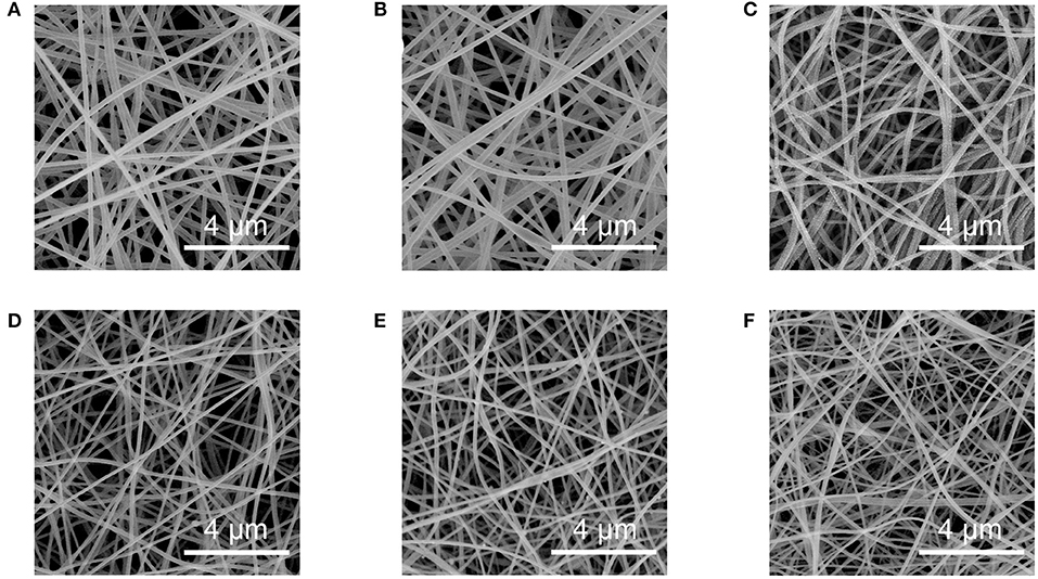
Figure 1. SEM images of the (A) as-spun, (B) stabilized, (C) C800, (D) C1000, (E) C1200, and (F) C1400 fibers.
Because XPS using an Al Kα source at 1486.6 eV can reveal the elemental composition of a sample at a depth of up to 10 nm from the sample surface, it is considered a powerful technique for surface elemental analysis (Shuguang, 1994; Tanuma et al., 2011). On the other hand, in SEM-EDX analysis using an accelerating voltage of 10 keV, the X-ray generation depth for carbon is ~1 μm (Goldstein et al., 2017; Monte-Carlo-Simulation, 2019). Thus, the surface and the bulk elemental compositions of the nanofibers were determined using XPS and SEM-EDX respectively, and the results are shown in Figure 2.
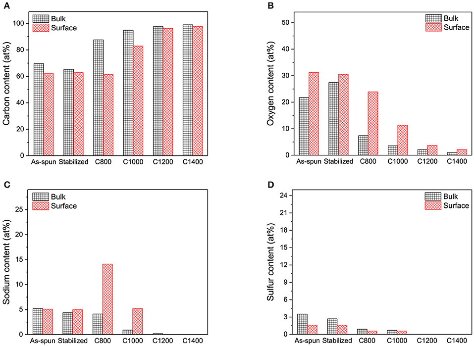
Figure 2. (A) Carbon, (B) oxygen, (C) sodium, and (D) sulfur contents in the bulk and on the surface of nanofibers.
The electrospun lignin-based nanofibers were mainly composed of carbon, oxygen, sodium, and sulfur. Overall, there were no significant differences between the bulk and surface chemical composition of the as-spun and stabilized nanofibers, indicating that the electrospun nanofibers had homogeneous composition along the axial direction, and the stabilization process did not add additional layers to the surface of the nanofibers. However, for C800 and C1000, oxygen and sodium contents on the surface were significantly higher than those in the bulk. The high-resolution SEM images in Figure 3 reveal heterogeneous dot-like features on the surfaces of C800 and C1000. These sodium- and oxygen-rich features were derived from the chemicals (NaOH, Na2CO3, and Na2SO4) used in the kraft process to extract lignin. Notably, homogeneity in the chemical composition of the carbon nanofibers was retained at carbonization temperatures above 1,200°C, indicating that such features can be effectively removed as the carbonization temperature increased.
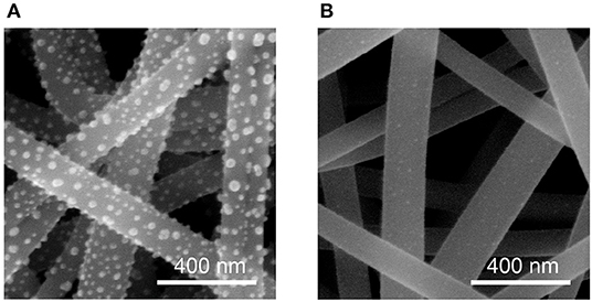
Figure 3. High-resolution SEM images showing dot-like features on the surface of (A) C800 and (B) C1000.
The cross-sectional images of all carbon nanofibers were captured by the FIB microscopy, and C1200 was chosen as a representative shown in Figures 4A,B because of its good fiber structure and relatively high carbon content according to the SEM and EDX results shown above. The carbon nanofibers were milled under a positively charged Ga ion beam to expose the cross-sections of the carbon nanofibers. As observed in Figure 4B, each nanofiber contained three distinct phases and the total fiber diameter was ~300 nm, which was double of that observed before Ga+ ion bombardment (Figure 1). The outer two layers were derived from the platinum foil used to enhance the milling quality. Under Ga+ ion beam exposure, platinum from the foil formed a thick layer on the surface of the nanofibers (Phase 1 in Figure 4B). Subsequently, Ga+ ions also penetrated the platinum layer, producing a new phase (Phase 2, PtxGay) (Phaneuf et al., 2003; Li, 2006), and the carbonized nanofibers formed the inner cores (dark contrast). Because of ion tunneling in carbon, significantly less amount of secondary electrons were generated, resulting in dark cores (Phase 3 in Figure 4B) (Serantoni et al., 2005; Li, 2006). Similar phenomena were also observed in FIB images for all other carbonized nanofibers (C800, C1000, and C1400). For further verification, cross-sectional SEM images of C1200 were recorded. It was first embedded in a conductive polymer, and then, immersed in liquid nitrogen for 1 min. Next, the deep-frozen sample was broken to expose the fracture surfaces of the carbon nanofibers, as shown in Figures 4C,D. As observed, the cross-sections of the carbon nanofibers were homogenous, with no voids, skin layers, or phase separation.
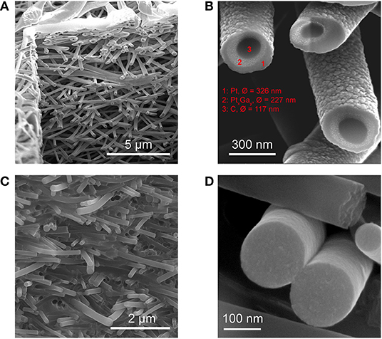
Figure 4. (A) FIB image of C1200 nanofibers, showing the milling box, (B) high-magnification FIB image of C1200 nanofibers, showing three distinct phases, (C) SEM image of C1200 nanofibers, showing the overall fracture surface, and (D) SEM image of fractured C1200 nanofibers.
TEM images of fractured edge of C800, C1000, C1200, and C1400 nanofibers are shown in Figures 5A–D. The inset images in Figures 5A–D also demonstrated that the fiber structure was homogenous and there was no obvious cavity observed. C800 and C1000 nanofibers contained some small curved graphene sheets as revealed by the contrast in the images. This suggested that C800 and C1000 nanofibers mostly contained amorphous carbon and some nanocrystalline graphite (De Tomas et al., 2017). The graphene sheets in C1200 and C1400 were longer and more obvious, as shown in Figures 5C,D; however, long-range stacking of graphene sheets was not observed, indicating that C1200 and C1400 predominantly contained nanocrystalline graphite but the formation of long-range ordered graphite structures did not occur in these samples (De Tomas et al., 2017). Similar trends have been reported by Zhang et al. (2017). They concluded that the lateral size of nano-graphene derived from kraft lignin increased with increasing temperature.
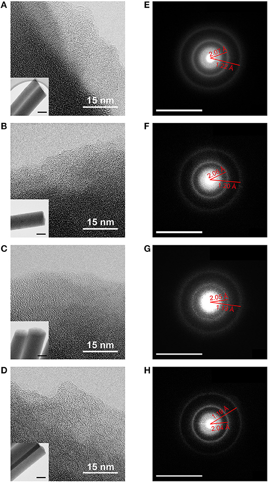
Figure 5. (A–D) TEM images of C800, C1000, C1200, and C1400, respectively. Scale bar in the inset: 100 nm. (E–H) SAED patterns of C800, C1000, C1200, and C1400, respectively. Scale bar: 12.5 nm−1.
The selected area electron diffraction (SAED) patterns of the carbon nanofibers are shown in Figures 5E–H. The smallest diffraction ring in the SAED pattern was assigned to the (002) planes. Notably, a prominent broadening effect was observed, which indicated loss of periodicity along the sheet-stacking direction of the graphitic structure (Matassa et al., 2014). Moreover, diffraction rings corresponding to (101) and (112) planes were detected, and the corresponding interplanar distances were calculated. The interplanar distances for the carbon nanofibers were mostly larger than those for graphite [2.04 Å for (101) planes and 1.16 Å for (112) planes] (Downs and Hall-Wallace, 2003). Moreover, with increasing carbonization temperature, the crystal planes were packed in a more compact manner (the (101) interplanar distance decreased from 2.07 to 2.04 Å). This indicated that high-temperature carbonization resulted in the formation of lignin-based carbon nanofibers with better structures.
Raman spectroscopy was performed to characterize the carbon structure of C800, C1000, C1200, and C1400 nanofibers. The intensity and position of Raman peaks were denoted by I and Pos, respectively. As observed in Figure 6, each sample exhibited three prominent Raman peaks, and the two most intense features are D peak at ~1,330 cm−1 and G peak at ~1,580 cm−1. The G peak was attributed to bond stretching of all pairs of sp2 atoms in rings and chains while the D peak was assigned to the breathing modes of sp2 atoms in the rings, which were activated by defects (Ferrari and Robertson, 2004). As observed in the TEM images (Figure 5), with increasing carbonization temperature from 800°C to 1,400°C, the carbon structure gradually evolved from amorphous carbon to nanocrystalline graphite. In this evolution stage, the upshift of Pos(G) from 1,576 to 1,588 cm−1 (Figure 6) indicated an increase in the degree of ordering in the carbon structure (Ferrari and Robertson, 2004). Moreover, because of the presence of the topological disorder in this stage, the Tuinstra and Koenig (TK) relation, which states that the I(D)/I(G) ratio is inversely proportional to the effective graphite crystallite size (La) was not valid. Instead, Farrari and Robertson proposed the relation: in 2000 (Tuinstra and Koenig, 1970; Ferrari and Robertson, 2000, 2004). As shown in Figure 6, the I(D)/I(G) ratio increased with increasing carbonization temperature from 800°C to 1,400°C. Thus, the effective size of nanocrystalline graphite increased as the carbonization temperature increased.
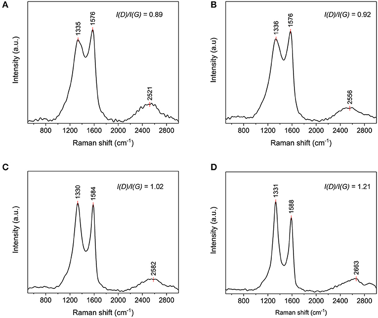
Figure 6. Raman spectra of (A) C800, (B) C1000, (C) C1200, and (D) C1400 fibers.
The Raman peaks at ~2,600 cm−1 (Figure 6) were assigned to 2D mode originating from four-step Stokes-Stokes double resonance Raman scattering (Yoon et al., 2011). The 2D peak typically reveals the electronic band structures and phonon dispersion of carbon materials and therefore, it can be used to characterize strain-induced anisotropy or distortion in the reciprocal lattice (Ferrari et al., 2006; Yoon et al., 2011). For instance, Yoon et al. reported that when strain was applied to graphene, the 2D peak redshifted, owing to the modification of the electronic band structure resulting from distortion (Yoon et al., 2011). Typically, the 2D peak appears at ~2,700 cm−1. However, in this study, it was observed at 2,521 cm−1 for C800, indicating carbon lattice distortion which was attributed to the incomplete conversion the lignin-based precursor to graphite during carbonization. As the carbonization temperature increased, the 2D peak monotonically shifted from 2,521 cm−1 for C800 to 2,663 cm−1 for C1400. The upshift of the 2D peak suggested that the carbon structures of the nanofibers became more ordered at higher carbonization temperatures. Moreover, it is reported that 2D peak is symmetric in turbostratic graphite because of the absence of the AB stacking order which induces the doublet structure (asymmetry) of the 2D peak (Cesano et al., 2016). Here, symmetric 2D peaks were observed for C800 and C1000 while the asymmetry of the 2D peak became more and more obvious in C1200 and C1400, again indicating more ordered carbon structures in C1200 and C1400.
Conclusion
Alkali lignin-based nanofibers were carbonized at four temperatures: 800, 1,000, 1,200, and 1,400°C, and different microscopic and spectroscopic techniques were performed to determine the differences in the structures of the obtained carbon nanofibers. It was confirmed that the electrospun lignin-based carbon nanofibers were dense and homogenous, without any phase separation. In addition, it was found that nanofibers carbonized at 800 and 1,000°C mostly contained amorphous carbon. Notably, carbonization at high temperatures (>1,200°C) facilitated the removal of non-carbon elements. Moreover, with increasing carbonization temperature, the degree of structural ordering of the nanofibers and the effective graphite crystal size increased. However, lack of periodicity along the sheet-stacking direction of the graphitic structure observed for the carbonized nanofibers. Thus, graphitization of these lignin-based nanofibers needs to be carried out at a higher temperature or in the presence of a catalyst.
Data Availability Statement
The datasets generated for this study are available on request to the corresponding author.
Author Contributions
The electrospinning, stabilization, and carbonization of the lignin-based nanofibers were conducted by JW, who also conducted SEM, EDX, and Raman analysis together with SG. The XPS was carried out by OP, and the FIB images were obtained by MK. JW, SG, MK, MH, and KO worked together for the TEM images. The results analysis and manuscript preparation were done by JW, SG, and KO.
Funding
Business Finland (Grelectronics), Bio4Energy (Swedish Strategy Research funding), and Swedish Research Council (Carbon Lignin 2017-04240).
Conflict of Interest
The authors declare that the research was conducted in the absence of any commercial or financial relationships that could be construed as a potential conflict of interest.
Acknowledgments
The authors gratefully acknowledge Business Finland (Grelectronics), Bio4Energy (Swedish Strategy Research funding), and the Swedish Research Council (Carbon Lignin 2017-04240) for the financial support.
References
Awal, A., and Sain, M. (2013). Characterization of soda hardwood lignin and the formation of lignin fibers by melt spinning. J. Appl. Polym. Sci. 129, 2765–2771. doi: 10.1002/app.38911
Baker, D. A., Gallego, N. C., and Baker, F. S. (2012). On the characterization and spinning of an organic-purified lignin toward the manufacture of low-cost carbon fiber. J. Appl. Polym. Sci. 124, 227–234. doi: 10.1002/app.33596
Baker, D. A., and Rials, T. G. (2013). Recent advances in low-cost carbon fiber manufacture from lignin. J. Appl. Polym. Sci. 130, 713–728. doi: 10.1002/app.39273
Braun, J., Holtman, K., and Kadla, J. (2005). Lignin-based carbon fibers: oxidative thermostabilization of kraft lignin. Carbon. 43, 385–394. doi: 10.1016/j.carbon.2004.09.027
Buckley, J. D., and Edie, D. D. (1993). Carbon-Carbon Materials and Composites. New Jersey, NJ: Noyes Publications.
Cesano, F., Rahman, M. M., Bardelli, F., Damin, A., and Scarano, D. (2016). Magnetic hybrid carbon via graphitization of polystyrene–co-divinylbenzene: morphology, structure and adsorption properties. ChemistrySelect 1, 2536–2541. doi: 10.1002/slct.201600278
Chand, S. (2000). Review carbon fibers for composites. J. Mater. Sci. 35, 1303–1313. doi: 10.1023/A:1004780301489
Dallmeyer, I., and Kadla, J. F. (2014). “Lignin-based carbon fibers,” in Handbook of Green Materials, eds K. Oksman, A. P. Mathew, A. Bismarck, O. J. Rojas, and M. Sain (Singapore: World Scientific), 25–41.
De Tomas, C., Suarez-Martinez, I., Vallejos-Burgos, F., López, M. J., Kaneko, K., Marks, N., et al. (2017). Structural prediction of graphitization and porosity in carbide-derived carbons. Carbons 119, 1–9. doi: 10.1016/j.carbon.2017.04.004
Doshi, J., and Reneker, D. H. (1995). Electrospinning process and applications of electrospun fibers. J. Electrostat. 35, 151–160. doi: 10.1016/0304-3886(95)00041-8
Downs, R. T., and Hall-Wallace, M. (2003). The american mineralogist crystal structure database. Am. Mineral. 88, 247–250. Available online at: https://pubs.geoscienceworld.org/msa/ammin/article-abstract/88/1/247/43886
Edie, D. (1998). The effect of processing on the structure and properties of carbon fibers. Carbon 36, 345–362. doi: 10.1016/S0008-6223(97)00185-1
Ferrari, A., Meyer, J., Scardaci, V., Casiraghi, C., Lazzeri, M., Mauri, F., et al. (2006). The raman fingerprint of graphene. Phys. Rev. Lett. 97:187401. doi: 10.1103/PhysRevLett.97.187401
Ferrari, A. C., and Robertson, J. (2000). Interpretation of Raman spectra of disordered and amorphous carbon. Phys. Rev. B 61:14095. doi: 10.1103/PhysRevB.61.14095
Ferrari, A. C., and Robertson, J. (2004). Raman spectroscopy of amorphous, nanostructured, diamond–like carbon, and nanodiamond. Philos. Trans. Royal Soc. Lond. Series A 362, 2477–2512. doi: 10.1098/rsta.2004.1452
Figueiredo, J. L., Bernardo, C. A., Baker, R., and Hüttinger, K. (2013). Carbon Fibers Filaments and Composites. Alvor: Springer Science & Business Media.
García-Mateos, F. J., Ruiz-Rosas, R., Rosas, J. M., Rodríguez-Mirasol, J., and Cordero, T. (2019). Controlling the composition, morphology, porosity, and surface chemistry of lignin-based electrospun carbon materials. Front. Mater. 6:114. doi: 10.3389/fmats.2019.00114
Goldstein, J. I., Newbury, D. E., Michael, J. R., Ritchie, N. W., Scott, J. H. J., and Joy, D. C. (2017). Scanning Electron Microscopy and X-ray Microanalysis. New York, NY: Springer. doi: 10.1007/978-1-4939-6676-9_27
Jia, Z., Lu, C., Liu, Y., Zhou, P., and Wang, L. (2016). Lignin/polyacrylonitrile composite hollow fibers prepared by wet-spinning method. ACS Sustainable Chem. Eng. 4, 2838–2842. doi: 10.1021/acssuschemeng.6b00351
Jiang, L. Y., Chung, T.-S., and Rajagopalan, R. (2007). Dual-layer hollow carbon fiber membranes for gas separation consisting of carbon and mixed matrix layers. Carbon 45, 166–172. doi: 10.1016/j.carbon.2006.07.008
Jin, J., Yu, B.-J., Shi, Z.-Q., Wang, C.-Y., and Chong, C.-B. (2014). Lignin-based electrospun carbon nanofibrous webs as free-standing and binder-free electrodes for sodium ion batteries. J. Power Sources 272, 800–807. doi: 10.1016/j.jpowsour.2014.08.119
Johnson, D. (1987). Structure-property relationships in carbon fibres. J. Phys. D Appl. Phys. 20:286. doi: 10.1088/0022-3727/20/3/007
Kai, D., Jiang, S., Low, Z. W., and Loh, X. J. (2015). Engineering highly stretchable lignin-based electrospun nanofibers for potential biomedical applications. J. Mater. Chem. B 3, 6194–6204. doi: 10.1039/C5TB00765H
Kumar, M., Hietala, M., and Oksman, K. (2019). Lignin-based electrospun carbon nanofibers. Front. Mater. 6:62. doi: 10.3389/fmats.2019.00062
Lai, C., Zhou, Z., Zhang, L., Wang, X., Zhou, Q., Zhao, Y., et al. (2014). Free-standing and mechanically flexible mats consisting of electrospun carbon nanofibers made from a natural product of alkali lignin as binder-free electrodes for high-performance supercapacitors. J. Power Sources 247, 134–141. doi: 10.1016/j.jpowsour.2013.08.082
Lallave, M., Bedia, J., Ruiz-Rosas, R., Rodríguez-Mirasol, J., Cordero, T., Otero, J. C., et al. (2007). Filled and hollow carbon nanofibers by coaxial electrospinning of alcell lignin without binder polymers. Adv. Mater. 19, 4292–4296. doi: 10.1002/adma.200700963
Li, J. (2006). The focused-ion-beam microscope—more than a precision ion milling machine. JOM 58, 27–31. doi: 10.1007/s11837-006-0156-z
Matassa, R., Orlanducci, S., Tamburri, E., Guglielmotti, V., Sordi, D., Terranova, M. L., et al. (2014). Characterization of carbon structures produced by graphene self-Assembly. 47, 222–227. doi: 10.1107/S1600576713029488
Monte-Carlo-Simulation (2019). Available online at: http://web.utk.edu/~srcutk/htm/simulati.htm (accessed September 20, 2019).
Phaneuf, M., Li, J., Shuman, R. F., Noll, K., and Casey, J. D. Jr. (2003). Apparatus and Method for Reducing Differential Sputter Rates. U.S. Patent No. 6,641,705.
Salinas-Torres, D., Ruiz-Rosas, R., Morallón, E., and Cazorla-Amorós, D. (2019). Strategies to enhance the performance of electrochemical capacitors based on carbon materials. Front. Mater. 6:115. doi: 10.3389/fmats.2019.00115
Serantoni, M., Sarac, A. S., and Sutton, D. (2005). FIB-SIMS investigation of carbazole-based polymer and copolymers electrocoated onto carbon fibers, and an AFM morphological study. Surface Coatings Technol. 194, 36–41. doi: 10.1016/j.surfcoat.2004.05.011
Sevastyanova, O., Qin, W., and Kadla, J. (2010). Effect of nanofillers as reinforcement agents for lignin composite fibers. J. Appl. Polym. Sci. 117, 2877–2881. doi: 10.1002/app.32198
Shimazaki, K. (1987). Active Carbon Fibers and Filter Adsorption Unit for Water Purification Comprising Said Fibers. U.S. Patent No. 4,696,742.
Shuguang, H. (1994). XPS nondestructive depth analysis method and its application in cement based composite materials. Cement Concrete Res. 24, 1509–1514. doi: 10.1016/0008-8846(94)90165-1
Tanuma, S., Powell, C., and Penn, D. (2011). Calculations of electron inelastic mean free paths. IX. Data for 41 elemental solids over the 50 eV to 30 keV range. Surface Interface Anal. 43, 689–713. doi: 10.1002/sia.3522
Tuinstra, F., and Koenig, J. L. (1970). Raman spectrum of graphite. J. Chem. Phys. 53, 1126–1130. doi: 10.1063/1.1674108
Usov, I., and Mezzenga, R. (2015). FiberApp: an open-source software for tracking and analyzing polymers, filaments, biomacromolecules, and fibrous objects. Macromolecules 48, 1269–1280. doi: 10.1021/ma502264c
Wang, S.-X., Yang, L., Stubbs, L. P., Li, X., and He, C. (2013). Lignin-derived fused electrospun carbon fibrous mats as high performance anode materials for lithium ion batteries. ACS Appl. Mater. Interfaces 5, 12275–12282. doi: 10.1021/am4043867
Yoon, D., Son, Y.-W., and Cheong, H. (2011). Strain-dependent splitting of the double-resonance Raman scattering band in graphene. Phys. Rev. Lett. 106:155502. doi: 10.1103/PhysRevLett.106.155502
Keywords: lignin, electrospinning, carbon nanofibers, renewable resources, microstructure
Citation: Wei J, Geng S, Kumar M, Pitkänen O, Hietala M and Oksman K (2019) Investigation of Structure and Chemical Composition of Carbon Nanofibers Developed From Renewable Precursor. Front. Mater. 6:334. doi: 10.3389/fmats.2019.00334
Received: 10 October 2019; Accepted: 05 December 2019;
Published: 19 December 2019.
Edited by:
Federico Cesano, University of Turin, ItalyReviewed by:
Patnarin Worajittiphon, Chiang Mai University, ThailandSaeed M. Alhassan, Khalifa University, United Arab Emirates
Roland Habchi, Lebanese University, Lebanon
Copyright © 2019 Wei, Geng, Kumar, Pitkänen, Hietala and Oksman. This is an open-access article distributed under the terms of the Creative Commons Attribution License (CC BY). The use, distribution or reproduction in other forums is permitted, provided the original author(s) and the copyright owner(s) are credited and that the original publication in this journal is cited, in accordance with accepted academic practice. No use, distribution or reproduction is permitted which does not comply with these terms.
*Correspondence: Kristiina Oksman, kristiina.oksman@ltu.se