- 1High School Affiliated to Nanjing Normal University, Nanjing, China
- 2China Jiliang University, Hangzhou, China
The research of wearable energy harvesting and storage devices has attracted tremendous attention from researchers with commercial wearable devices emerging in the life as new mainstream. Among them, shoes are a better choice for energy harvesting. However, most of the existing energy harvesting and storage shoes have complex structures, poor wearing comfort, and high cost. In order to solve these problems, a kind of innovative multi-functional shoes is developed and discussed in this paper. The shoe contain two main parts. One is a rubber column used as heel material, which plays a role in cushioning and damping during movement and making the shoe more comfortable to wear. The other one is a circuit system designed to realize energy harvesting, energy storage, and emergency charging of electronic products during walking. The performance test of the rubber column is carried out, and then the structure and geometric size of the rubber column is optimized according to its performance, human weight, and gait. Finally, the stress and energy harvesting of the multi-functional shoes in different gait conditions are analyzed. The analysis results show that the developed innovative multi-functional shoe has good stability and versatility when working under different gait, and the rubber column is beneficial to improve the wearing comfort of energy harvesting shoes.
Introduction
The development of technology has increased the use of commercial wearable devices yet short battery life of these electronics products is still a bothering problem (Kamiyama and Murakami, 2018). At present, energy harvesting from human locomotion has been proven to be a convenient and promising way to continuously power wearable electronics products (Moro and Benasciutti, 2010; Bai et al., 2013; Ylli et al., 2015; Halima et al., 2018). Various applications including but not limited to shoes (Paul et al., 2015; Qian et al., 2018; Turkmen and Celik, 2018), clothing (Heo et al., 2017), backpack (Yuan et al., 2018), and insoles (Luo et al., 2015; Johari and Rashid, 2017), have been exploited to convert human-generated mechanical energy to electrical energy. Among them, shoes are an indispensable daily necessities in people's lives. It has attracted great attention from the research community as an energy harvester. Because people generate a lot of energy when they walk and collecting energy through shoes is relatively simple and effective, the idea of charging electronic products with shoes emerged. The energy generated by the progress of walking can be converted into electrical energy to charge electronic products.
There are two methods commonly used in shoe energy harvesting, i.e., piezoelectric and electromagnetic. The piezoelectric material is a smart material which generates electrical charges under strain changes when subjected to pressure, and electrodes can collect electrical charges to produce electrical current. In energy harvesting shoe, the piezoelectric material is placed where stress and strain are generated by walking, such as soles and heels. Qian et al. (2018) presented an embedded piezoelectric footwear harvester with optimized force amplification frame. The experimental results show that the 8- and 6-layer heel footwear harvesters have an average power output of 7 mW/shoe and 9 mW/shoe at a walking speed of 4.8 km/h. Rocha et al. (2009) reported the use of piezoelectric materials electroactive beta-polyvinylidene fluoride production soles as energy collection elements, from the footsteps to collect energy. Cha and Seo (2018) even integrated the piezoelectric energy transducer into the slippers to collect the energy generated by the bending of the slippers, and verified the feasibility of the design through experiments. At the same time, the research on the energy collected by electromagnetic methods in shoes is also extensive. For an energy harvesting shoe using an electromagnetic harvester, the force generated by walking drives the magnet to move relative to the coil, thereby generating an induced current. Zhu et al. (2018) reported a compact electromagnetic in-shoe energy harvester using wave spring and rotational electrical generator. An average energy of 55.6 μJ and the peak power of 1.6 mW was generated by each footstep. Xie and Cai (2015) reported an in-shoe magnetic harvester that generated electricity from a microgenerator driven by a special trapezoidal slider mechanism and a gear train. Experiments showed that the harvester could produce an average power output of about 1 W during normal walking. Baghbani and Ashoorirad (2009) designed a mobile electronic power generation system that used a combination of a rotary arm, a stepped-up gearbox and a small rotational electrical generator. Both methods are available to generate electricity to fill up the power. However, the piezoelectric could only generate electricity in a limited power, which requires a significant amount of steps to fill the power. Therefore, this method could be adopted in powering micro devices with low power consumption (Gatto and Frontoni, 2014; Meier et al., 2014), but not suitable for charging batteries with large capacity. Moreover, it has been reported that electromagnetic energy harvesting shoes have a relatively high energy harvesting efficiency, but they have significant interference with the user's normal gait when used (Carroll and Duffy, 2012). In addition, there are many other ways to use energy harvesting shoes: for example, Bonisoli et al. (2017) used an integrated cylinder to capture the energy produced by a shoe striking the ground. The cylinder consists of a magneto inductive transducer embedded in an electronic interface. Fu et al. (2016) used an air bladder-turbine to collect the airflow caused by the heel impact and convert it into electrical energy. It was verified by experiments that the airflow energy harvester worked stably and reliably.
In this paper, a kind of innovative multi-functional shoes is developed. In the shoe, there are two main parts. One is rubber column used as heel material, which plays a role in cushioning and damping during movement and making the shoe more comfortable to wear. The other one is a circuit system designed to realize energy harvesting, energy storage, and emergency charging of electronic products during walking. The performance test of the rubber column is carried out. And then the structure and geometric size of the rubber column is optimized according to its performance, human weight, and gait. Finally, the stress and energy harvesting of the multi-functional shoes in different gait conditions are analyzed. The analysis results show that the developed innovative multi-functional shoe has good stability and versatility when working in different gait, and the rubber column is beneficial to improve the wearing comfort of energy harvesting shoes.
Design on Innovative Multi-Functional Shoes
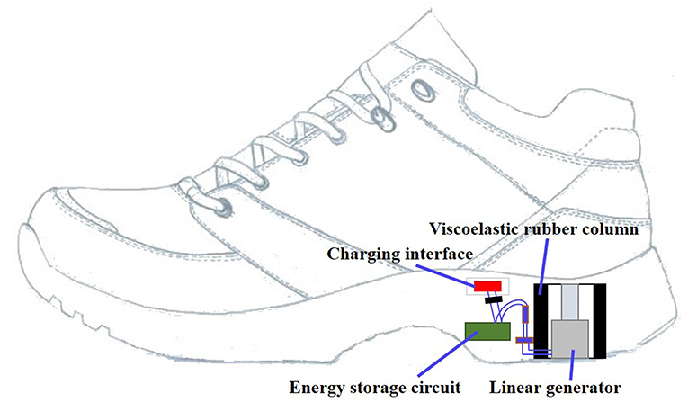
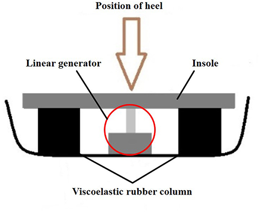
The main function of innovative multi-functional shoes is to collect electric energy continuously during people's walking process, and at the same time to ensure the comfort of people walking. In order to achieve these functions, the multi-functional shoe mainly consists of the rubber column and the power acquisition device which consists of a linear generator, a storage circuit and a charging interface, as shown in Figure 1. At the heel of the shoe, a ring shaped rubber column is placed inside. And a linear generator is placed at the center of the ring. The solid insole is placed above the rubber column and is directly connected to the rubber column and the movable part of the linear generator, as shown in Figure 2.
Design of Rubber Column
The rubber column is made into a ring shape, so the power acquisition device can be placed in the middle of the rubber column ring. The rubber column ring is made of viscoelastic materials. The material is kind of passive damping material with certain stiffness and damping. That means, the material has the compression type variable similar to the spring. When an external force is applied to the viscoelastic material, it is compressed and deformed; when the external force is removed, it can quickly return to its original state. When the viscoelastic materials is constantly deformed, its damping characteristics can reduce vibration and have a cushioning effect. Therefore, the use of the viscoelastic rubber column as a heel support material can reduce the impact during exercise and improve the comfort of the shoe.
Design of the Power Acquisition Device
The power acquisition device is a circuit system consisting of a linear generator, a storage circuit and a charging interface. The circuit system enable energy harvesting and storage during exercise, and then realize emergency charging of electronic products.
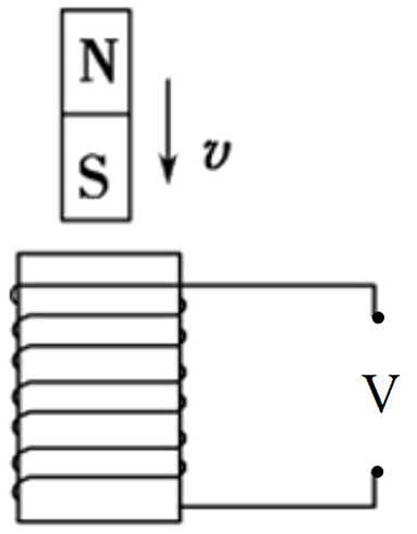
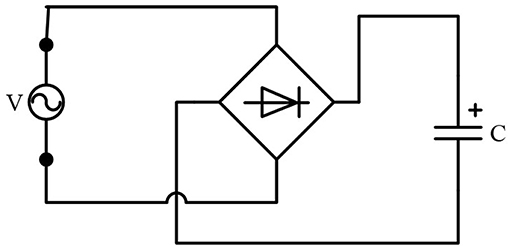
The power acquisition device is placed on the heel and the central axis of the linear generator is perpendicular to the sole. The principle of the linear generator is shown in Figure 3. The two series connected coils of the linear generator are symmetrically wound to the guide device in the opposite direction, resulting in the same phase of the electrical signals produced in the two coils. During walking, the movement of the permanent magnet in the linear generator is caused by the force of the heel received by the shoe containing the energy harvester. The movement of the permanent magnet causes a change in the flux linkage in the coil, thus inducing a voltage between the ends of the coil. The linear generator is also connected to a bridge rectifier to charge a capacitor, as shown in Figure 4. Schottky diodes are used in the bridge rectifier due to their threshold voltage. DC voltage after tuning by the bridge rectifier:
Energy stored in the capacitor can be calculated:
Where, V0 is the voltage generated by the linear generator, E is energy stored in the capacitor, C is the capacitance and V is the voltage across of the capacitor. In this paper, the electrolytic capacitor with a withstand voltage of 35 V and a capacity of 100 μF is selected. The maximum energy storage of the electrolytic capacitor:
As mentioned above, the solid insole is placed above the rubber column and is directly connected to the rubber column and the moveable part of the linear generator, as shown in Figure 2. When the heel moves down, the solid insole is pushed down. With the solid insole moving down, the rubber column is gradually compressed and the linear generator moves vertically downward. When the heel lifts up, the elasticity of the rubber column will restore it to the initial state, while the linear generator is driven to move vertically upward. In this reciprocating motion process, the moveable part of the linear generator also reciprocates to continuously generate electrical energy. Compared with the rotational generator (Baghbani and Ashoorirad, 2009; Zhu et al., 2018), the linear generator is used as the energy generating device, and it is not necessary to convert the linear motion into a rotary motion, simplifying the structure and increasing the energy conversion rate.
Test on Rubber Column
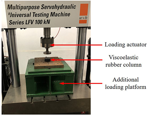
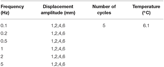
The viscoelastic material is a high molecular polymer that dissipates vibration energy during deformation and has both viscous and elastic properties. Because the rubber column uses a highly damped viscoelastic material, it has a vibration damping function, which can cushion and reduce vibration, reduce sports impact and improve the comfort of the shoes. In order to determine the performance parameters of the rubber column, the mechanical properties of a cylindrical viscoelastic material are tested under sinusoidal load of different frequencies and displacement amplitudes on the fatigue testing machine, as shown in Figure 5. The diameter and the thickness of the cylindrical viscoelastic material are 70 and 35 mm, respectively. And the loading conditions of the test are shown in Table 1.
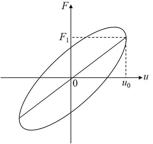
Ideally, the force-displacement relationship of viscoelastic material under axial sinusoidal load is an ellipse, as shown in Figure 6. It can be deduced from Figure 6 that the equivalent stiffness of viscoelastic materials is:
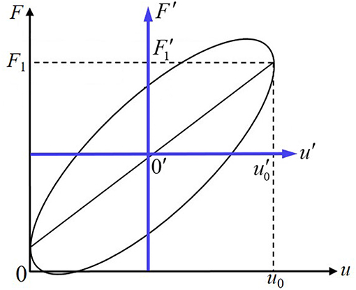
Where, u0 is the maximum vertical displacement of viscoelastic materials, F1 is the force generated by the viscoelastic material when the displacement is u0. In this test, since the viscoelastic material is only pressed and not pulled, the force and displacement values for each point on the curve are positive, and the origin of the coordinate is not at the center of the ellipse. When processing data, the local coordinate system F'- u' can be established with the center of the curve as the origin, as shown in Figure 7. Let the origin 0' coordinate of the local coordinate system be (x, y), the formula for calculating the equivalent stiffness of viscoelastic materials under compression in local coordinate system can be derived:
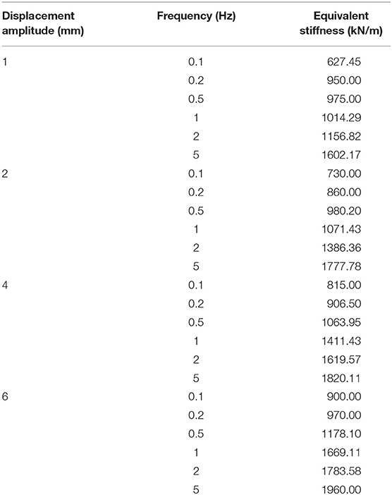
Figure 8 shows the force-displacement hysteretic curves under different frequencies and displacement amplitudes. Table 2 shows the equivalent stiffness of the rubber column at the same displacement amplitude and different frequencies. Figure 9 shows the rubber column compression and recovery deformation test at amplitude 20 mm and frequency 1 Hz.
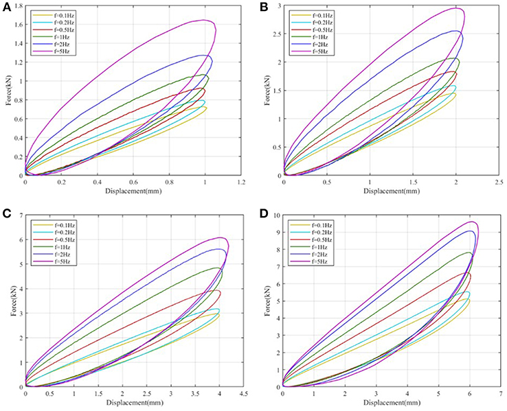
Figure 8. Hysteretic curves under different frequencies and displacement amplitudes. (A) 1 mm, (B) 2 mm, (C) 4 mm, (D) 6 mm.

Figure 9. Viscoelastic rubber column compression and recovery deformation test. (A) Deformation at amplitude 20 mm and frequency 1 Hz. (B) Deformation recovery capability after unloading.
It can be seen from Figure 8 and Table 2 that the equivalent stiffness gradually increases with increasing frequency and displacement amplitude of the sinusoidal load. These results show that the rubber column can provide greater rigidity under high frequency vibration, that is, it can effectively isolate and reduce vibration. It can be seen from Figure 9 that under the action of large displacement amplitude, the rubber column can withstand more than 57% of the compression displacement, and the thickness of the rubber column after unloading can be restored to the state before loading. The deformation of the material can be completely restored, and the material is still in the stage of elastic work. It indicates that the rubber column has strong elasticity and deformation recovery ability.
Force Analysis and Energy Harvesting
In this paper, the size of the rubber column ring affects its stiffness and the deformation of the force, which indirectly affects the energy harvesting of the energy harvester. Here, the rubber column has been selected a diameter of 70 mm and an overall static height of 35 mm, which is similar to most sports heel heights and widths. In slow walking, the average single-leg force of a 70 kg male walking is 700 N, and the deformation of the rubber column is required to be 5 mm. When the equivalent stiffness of the rubber column is determined, the shape variable under the external force can be expressed as:
Where, x is the compressed variable, and its unit is mm; F is the external force, and its unit is N. Therefore, the rubber column ring designed in this paper needs to have a stiffness of 140 N/mm. When the height of the rubber column is constant, its stiffness is proportional to the upper surface area. From the above, the stiffness data of a rubber column having a diameter of 70 mm and a height of 35 mm at different frequencies and different displacements is known. In the slow walking, referring to 0.1 HZ, the stiffness data under the loading condition of 6 mm is 900 N/mm. The planar circular area of the rubber column:
Where, D is the diameter of the rubber column. It is desirable that the rubber column ring has a stiffness of 140 N/mm. The size of the rubber column ring is calculated as follows:
The upper circular surface area of the rubber column:
The upper circular surface area of the rubber column ring:
The diameter of the inner cylindrical hole:
Take the diameter of the inner cylindrical hole to be 64 mm, the upper circular surface area of the rubber column ring:
The calculated stiffness at this time:
Therefore, the shape variable of the rubber column ring at 700 N:
From the above calculation, the rubber column ring of 35 mm in height has an outer diameter of 70 mm and an inner hole diameter of 64 mm.
In this paper, the linear generator is placed on the central axis of the inner bore of the rubber column ring. The two series-connected coils of the linear generator are symmetrically wound in the opposite direction to the guiding device, and the coil guiding device has a specification of D50 × 25 mm. The coil is evenly wound by a 75 μm copper enameled wire with two series 1,000 turns. The permanent magnet in the linear generator is an N35 nickel-plated NdFeB magnet with a specification of D45 × 10 mm and a residual magnetization Br of 1.21T. The linear generator generates electricity according to the electromagnetic effect is shown in Figure 3. When the closed circuit is n-turn coil, the instantaneous electromotive force can be expressed as:
Where, V0 is the induced electromotive force generated, and its unit is V; n is he number of turns of the coil; ΔΦ is the amount of change in the magnetic flux, and its unit is Wb; Δt is the time taken to change, and its unit is s. In a uniform magnetic field, the product of the magnetic induction B of the magnetic field and the area Sm of the direction perpendicular to the magnetic field is called the magnetic flux passing through this surface:
Where, the unit of Φ is Wb, the unit of B is T and the unit of Sm is m2.
In the 1 s 1-step slow walking, the average single-leg force of a 70 kg male walking is 700 N, and the shape variable of the rubber column ring is 4.74 mm. Assuming that the permanent magnet is a uniform magnetic field, the magnetic field strength B is 1.21T, and the coil with a diameter of 50 mm is two series 1,000 turns. Moreover, when walking 1 step, the pressing and lifting time of the foot is equal. The voltage generated and energy harvested by the walking step is calculated as follows:
The area of the coil perpendicular to the direction of the magnetic field:
When the shape variable is 4.74 mm, the number of effective coils in the magnetic field:
The voltage generated by the 2 series coils in the 1-step of pressing and lifting:
The DC voltage after tuning by the bridge rectifier:
The energy charged by the 1-step in the capacitor:
The energy charged by the 1 second in the capacitor:
The 100 μF electrolytic capacitor full of energy time:
The same situation can be calculated from the above studies. The energy harvesting in slow running and normal running is shown in Table 3. In 1 second 2-steps slow running, the average single foot force of a 70 kg male walking is 500 N. With reference to 0.5 HZ, and the stiffness data of the rubber column under loading of 4 mm is 1063.95 N/mm. It can be calculated that the stiffness of the rubber column ring at this time is 174.5 N/mm, and the deformation of the 500 N force is 2.87 mm. Also, it can be calculated that the DC voltage generated in 1 step can reach 3.932 V and the energy charged can reach 773.0 μJ. It can fill 100 μF electrolytic capacitor in about 40 s. Similarly, in 1 s 4-steps normal running, the average single-leg force of a 70 kg male running is 350 N, with reference to 2 HZ, and the stiffness data of the rubber column under loading of 2 mm is 1386.36 N/mm. It can be seen from the calculation that the stiffness of the rubber stud at this time is 227.36 N/mm, and the deformation of the 350 N force is 1.54 mm. It is calculated that the voltage generated by the 1-step compression force and the restoring force can reach 4.711 V. Regardless of the damage of energy, the voltage generated by the generator is theoretically 4.240 V after passing through the bridge rectifier, at this time, the energy charged of the capacitor is 898.9 μJ. It only takes 18 s to fill a 100 μF electrolytic capacitor.
Concluding Remarks
After research and analysis, the innovative multi-functional shoes analyzed in this paper uses the linear generators for energy harvesting, which simplifies the structure and improves the energy conversion rate. The heel support material adopts a rubber column, which satisfies the compression type variable similar to the spring and also reduces the impact of motion that increases the comfort of the shoes. Moreover, the rubber column is similar in material to the sole itself, so there is no compatibility problem and durability increases. This innovative multi-purpose shoe is a versatile shoe that combines charging, vibration reduction and heightening.
Data Availability
The datasets generated for this study are available on request to the corresponding author.
Author Contributions
BX proposed the idea of the paper, completed the test, analyzed some experimental data, and wrote the paper. YL completed some of the writing of the article and the analysis of the experimental data.
Conflict of Interest Statement
The authors declare that the research was conducted in the absence of any commercial or financial relationships that could be construed as a potential conflict of interest.
References
Baghbani, R., and Ashoorirad, M. (2009). “A power generating system for mobile electronic devices using human walking motion,” in 2009 Second International Conference on Computer and Electrical Engineering (Dubai: IEEE), 2, 385–388. doi: 10.1109/ICCEE.2009.58
Bai, P., Zhu, G., Lin, Z. H., Jing, Q., Chen, J., Zhang, G., et al. (2013). Integrated multilayered triboelectric nanogenerator for harvesting biomechanical energy from human motions. ACS Nano 7, 3713–3719. doi: 10.1021/nn4007708
Bonisoli, E., Repetto, M., Manca, N., and Gasparini, A. (2017). Electro-mechanical and electronic integrated harvester for shoes application. IEEE/ASME Transac. Mechatr. 22.5, 1921–1932. doi: 10.1109/TMECH.2017.2667401
Carroll, D., and Duffy, M. (2012). Modelling, design, and testing of an electromagnetic power generator optimized for integration into shoes. Proc. Instit. Mech. Eng. Part I J. Syst. Control Eng. 226, 256–270. doi: 10.1177/0959651811411406
Cha, Y., and Seo, J. (2018). Energy harvesting from a piezoelectric slipper during walking. J. Intell. Mater. Syst. Struc. 29, 1456–1463. doi: 10.1177/1045389X17740962
Fu, H., Cao, K., Xu, R., Bhouri, M. A., Martínez-Botas, R., and Kim, S. -G. (2016). “Footstep energy harvesting using heel strike-induced airflow for human activity sensing,” in 2016 IEEE 13th International Conference on Wearable and Implantable Body Sensor Networks (BSN) (San Francisco, CA: IEEE), 124–129. doi: 10.1109/BSN.2016.7516245
Gatto, A., and Frontoni, E. (2014). “Energy Harvesting system for smart shoes,” in 2014 IEEE/ASME 10th International Conference on Mechatronic and Embedded Systems and Applications (MESA). (Senigallia: IEEE), 1–6.
Halima, M. A., Rantza, R., Zhang, Q., Gu, L., Yang, K., Roundy, S., et al. (2018). An electromagnetic rotational energy harvester using sprung eccentric rotor, driven by pseudo-walking motion. Appl. Energy 217, 66–74. doi: 10.1016/j.apenergy.2018.02.093
Heo, J. S., Eom, J., Kim, Y. H., and Park, S. K. (2017). Recent progress of textile-based wearable electronics: a comprehensive review of materials, devices, and applications. Small 14:1703034. doi: 10.1002/smll.201703034
Johari, J., and Rashid, T. M. A. T. (2017). “Optimization of piezoelectric transducer placement in shoe insole for energy harvesting,” in 2017 International Conference on Electrical, Electronics and System Engineering (ICEESE). (Kanazawa: IEEE), 61–66.
Kamiyama, K., and Murakami, T. (2018). “An approach to energy harvesting considering passive action during walking,” in 2018 12th France-Japan and 10th Europe-Asia Congress on Mechatronics (Tsu: IEEE), 277–282. doi: 10.1109/MECATRONICS.2018.8495832
Luo, Z., Zhu, D., and Beeby, S. P. (2015). “Multilayer ferroelectret-based energy harvesting insole,” in Journal of Physics: Conference Series (Boston, MA: IOP Publishing), 660:012118. doi: 10.1088/1742-6596/660/1/012118
Meier, R., Kelly, N., Almog, O., and Chiang, P. (2014). “A piezoelectric energy-harvesting shoe system for podiatric sensing,” in 2014 36th Annual International Conference of the IEEE Engineering in Medicine and Biology Society (Chicago, IL: IEEE) 622–625. doi: 10.1109/EMBC.2014.6943668
Moro, L., and Benasciutti, D. (2010). Harvested power and sensitivity analysis of vibrating shoe-mounted piezoelectric cantilevers. Smart Mater. Struc. 19:115011. doi: 10.1088/0964-1726/19/11/115011
Paul, P. J., Tutu, R. S. D., Richards, W. K., Jerome, V. M., et al. (2015). “Project power shoe: piezoelectric wireless power transfer—A mobile charging technique,” in 2015 IEEE Global Humanitarian Technology Conference (GHTC) (Seattle, WA: IEEE), 334–339. doi: 10.1109/GHTC.2015.7343993
Qian, F., Xu, T. B., and Zuo, L. (2018). Design, optimization, modeling and testing of a piezoelectric footwear energy harvester. Energy Conver. Manage. 171, 1352–1364. doi: 10.1016/j.enconman.2018.06.069
Rocha, J. G., Goncalves, L. M., Rocha, P. F., Silva, M. P., and Lanceros-Mendez, S. (2009). Energy harvesting from piezoelectric materials fully integrated in footwear. IEEE Trans. Industr. Electronics 57, 813–819. doi: 10.1109/TIE.2009.2028360
Turkmen, A. C., and Celik, C. (2018). Energy harvesting with the piezoelectric material integrated shoe. Energy 150, 556–564. doi: 10.1016/j.energy.2017.12.159
Xie, L., and Cai, M. (2015). An in-shoe harvester with motion magnification for scavenging energy from human foot strike. IEEE/ASME Transac. Mechatronics 20, 3264–3268. doi: 10.1109/TMECH.2015.2428618
Ylli, K., Hoffmann, D., Willmann, A., Becker, P., Folkmer, B., Manoli, Y., et al. (2015). Energy harvesting from human motion: exploiting swing and shock excitations. Smart Mater. Struc. 24:025029. doi: 10.1088/0964-1726/24/2/025029
Yuan, Y., Liu, M., Tai, W. C., and Zuo, L. (2018). Design and treadmill test of a broadband energy harvesting backpack with a mechanical motion rectifier. J. Mech. Design 140:085001. doi: 10.1115/1.4040172
Keywords: multi-functional shoe, rubber column, energy harvesting, linear generator, storage device
Citation: Xu B and Li Y (2019) Force Analysis and Energy Harvesting for Innovative Multi-functional Shoes. Front. Mater. 6:221. doi: 10.3389/fmats.2019.00221
Received: 18 July 2019; Accepted: 26 August 2019;
Published: 11 September 2019.
Edited by:
Dingshan Yu, Sun Yat-sen University, ChinaReviewed by:
Zhonghua Xiang, Beijing University of Chemical Technology, ChinaYuan Chen, University of Sydney, Australia
Copyright © 2019 Xu and Li. This is an open-access article distributed under the terms of the Creative Commons Attribution License (CC BY). The use, distribution or reproduction in other forums is permitted, provided the original author(s) and the copyright owner(s) are credited and that the original publication in this journal is cited, in accordance with accepted academic practice. No use, distribution or reproduction is permitted which does not comply with these terms.
*Correspondence: Borui Xu, brxu2002@163.com
 Borui Xu
 Yang Li