
95% of researchers rate our articles as excellent or good
Learn more about the work of our research integrity team to safeguard the quality of each article we publish.
Find out more
ORIGINAL RESEARCH article
Front. Mater. , 04 September 2019
Sec. Mechanics of Materials
Volume 6 - 2019 | https://doi.org/10.3389/fmats.2019.00214
Surface instability via wrinkle formation is a common feature in thin films attached to a compliant substrate. Wrinkled thin-film structures have been increasingly exploited to enhance device performance. In this study, a numerical technique utilizing embedded imperfections is employed for direct simulations of wrinkle formation, extending from a single-film structure to composite films involving two or more layers. The incorporation of material elements, bearing different elastic properties at the film-substrate interface, assists in triggering buckling instability when the compressive strain reaches a critical value. The wrinkle wavelength and amplitude obtained from the numerical modeling show excellent agreements with available theoretical solutions involving bi-layer composite films, over the entire span of volume ratios of the constituent layers. A valid range of imperfection distribution, resulting in uniform wrinkle formation, is identified. The current numerical approach is robust and easy to implement and yields great promises in generating reliable wrinkling patterns. It can be readily applied to cases where realistic features cannot be captured by theories, such as the generalized plane strain deformation, indirect compression, and multilayer composite films.
Surface instability in the form of wrinkle formation is a common feature in thin films attached to a compliant substrate. In polymer-based photovoltaic (PV) and optoelectronic systems, surface wrinkling is increasingly exploited to enhance the device performance. A wrinkled structure has been shown to increase light harvesting efficiency for organic PV layers (Lipomi et al., 2011; Kim et al., 2012; Ji et al., 2018) and improved light extraction in organic light-emitting diodes (Ji et al., 2018). In the case of “hard” PV and/or conducting layers such as silicon, perovskite, and indium tin oxide, various ways of fabricating them onto an instability-driven wrinkled base structure, for the purpose of enhancing light trapping (Ram et al., 2017; Bush et al., 2018; Schauer et al., 2018; Zhang et al., 2018) or scattering (Wang C. et al., 2017), have been reported. An added benefit of the wrinkled structure is the possible improvement in deformability in stretchable electronics (Wang B. et al., 2017); thus enabling their potential deployment in fabrics and on curved or uneven surfaces. Some recent studies have demonstrated the mechanical robustness upon stretching, bending, and cyclic deformation while retaining reasonable optoelectronic performances (Kaltenbrunner et al., 2012; Hsieh et al., 2018; Ryu and Mongare, 2018). Wrinkling instabilities have also been reported for dielectric elastomers (Zhu et al., 2012; Zurlo et al., 2017).
Surface wrinkling can be induced over a large area at low cost. A commonly adopted fabrication technique is to deposit the thin films on a pre-stretched elastomeric substrate. Upon relaxation the film is under compression. If the compressive strain (determined by the extent of pre-stretch) exceeds a critical value, wrinkling instability will be triggered to reduce the elastic strain energy. Controlling wrinkle formation is thus of great importance, which calls for robust numerical design tools capable of taking into account a wide range of geometric and material features of the multilayer film-substrate systems.
There are inherent challenges associated with modeling instabilities using the finite element analysis. In some studies, the surface wrinkling phenomenon was simulated using a two-step process involving pre-buckling and post-buckling analyses (Mei et al., 2011; Cao and Hutchinson, 2012b; Bayat and Gordaninejad, 2015; Saha, 2017). The linear modal analysis was conducted for the pre-buckling step, and the post-buckling analysis was carried out using a combination of non-linear material/geometric models and the imperfection techniques. For instance, for the post-buckling step, the incompressible neo-Hookean material model were exploited for both film and substrate, that require the use of incompressible/hybrid elements (Cao and Hutchinson, 2012b). As reported in Cao and Hutchinson (2012b), the results of such models are quantitatively different from other non-linear elastic material models, and only comparable to other (incompressible) linear elastic film material models for very stiff films compared to the substrate. In addition, although employing such elements may have benefits within the reported numerical framework as to simulating the higher-order deformation modes at large strains, incompressible/hybrid elements are available only in limited finite element packages such as ABAQUS. These approaches are often based on relatively complex theories and are computationally more expensive compared to techniques using regular elements. Moreover, they are applicable only for the static analysis, and can lead to convergence issues when used with material models that exhibit volumetric plasticity (Abaqus, 2017). Aside from the type of elements, other special treatments are required to capture the bifurcation and post-bifurcation wrinkling shapes. The geometrical imperfection method, employed more frequently for studying surface instability, may include the mesh, geometry, and boundary condition perturbation techniques. For instance, a sinusoidal perturbation was directly imposed on the geometry of the film layer which dictates the formation/propagation of sinusoidal-form waves (Huck et al., 2000; Bayat and Gordaninejad, 2015). In another study, two different types of sinusoidal imperfection and a periodic array of non-interacting exponential surface depressions were specified within the model and studied separately (Cao and Hutchinson, 2012a). In a similar fashion, a mesh perturbation technique was applied in that the mesh nodal points were displaced by the sinusoidal perturbation displacement field function (Saha, 2017). All such imperfection-based approaches are relatively complex, and they essentially build the formation of sinusoidal waves into the model. The implementation can be laborious and requires calibration by setting many free parameters. A more straightforward approach was reported, which however involved special geometric features built into the film surface (Zheng et al., 2010). Aside from the aforementioned geometrical approach, the material imperfection approach is typically based on perturbation via the damage and/or plasticity techniques. As an example, a non-uniform plastic behavior was built into the model containing an elastoplastic film (Cao et al., 2012). Analytical models based on the energy minimization approach have also been reported to predict compression induced wrinkling and dielectric breaking in electroactive polymeric thin films (De Tommasi et al., 2014).
All the aforementioned numerical modeling approaches were applied to a single-layer film scenario. Simulations of wrinkling become even more challenging when multilayer thin films are involved. As a consequence, there are very few finite element studies addressing the surface instabilities in a composite thin film/compliant substrate system. For instance, the wrinkling of a bilayer film on a soft substrate was studied in Jia et al. (2012), limited only to a linear modal analysis.
The present paper reports a straightforward finite element modeling approach to simulate temporal evolution of wrinkling. In this embedded imperfection approach, some elements with perturbed material properties are distributed at the film-substrate interface so as to trigger the wrinkling deformation modes. In this study, all thin film and substrate materials are assumed to follow linear elasticity. It was built upon our previous development (Nikravesh et al., 2019) but now involves higher-order finite elements, more realistic model layouts with a composite film stack, and a systematic analysis on the effect of imperfection properties and distribution. The assumption of linear elasticity for the entire film-substrate system may not be realistic from the physical standpoint (Hutchinson, 2013). However, this assumption was necessary at the current stage of our model development, to avoid complexities and be able to verify the numerical modeling approach when compared with the well-accepted linear elastic analytical models. Once the reliability of the proposed approach is proven for the linear elastic case, more complex non-linear material models may be explored in futures studies.
In the presentation below we first provide a theoretical overview of wrinkle formation for the single-film and bilayer composite film systems. The numerical model description then follows. Verification of numerical results using the single-film model, and explorations of wrinkling wavelength, critical strain, and evolution of amplitude for the case of composite films are then presented. A sensitivity analysis on the properties and placement of imperfections, as well as the general applicability of the current approach, are also included.
The problem of surface wrinkling of a single-layer film on top of a compliant substrate has been analytically studied, and some approximate planar solutions are available in the literature (Biot, 1965; Volynskii et al., 2000; Groenewold, 2001; Chung et al., 2011; Wang et al., 2016). Fewer analytical studies have been reported regarding the case of multilayer composite films. There have been attempts to correlate the solutions of the surface instability of a single-layer film problem to the bilayer and multilayer film scenarios, via the derivation of the effective modulus of the multilayer film stack considering the composite beam/plate theories (Stafford et al., 2005; Nolte et al., 2006; Huang et al., 2007; Lejeune et al., 2016). Here, a brief overview of the theories is presented.
Consider a semi-infinite film-substrate system under direct compression as shown in Figure 1A. The surface instability of a single-layer film on top of a compliant substrate has been analytically characterized by the key wrinkling parameters (Biot, 1965; Volynskii et al., 2000; Groenewold, 2001; Chung et al., 2011) as follows
where the parameters λ, ecr, and A are, respectively, the wavelength, critical buckling compressive strain, and the amplitude of the wrinkles. Note that in Equations (1–3), Es and νs are, respectively, Young's modulus and Poisson's ratio of the substrate; Ef, νf, and tf are, respectively, Young's modulus, Poisson's ratio, and the thickness of the single-layer film.

Figure 1. Schematics showing the formation of buckles (wrinkles) during (A) compression along the x-direction and (B) applied tension along the z-direction. The scenarios in (A,B) are also termed direct compression and indirect compression, respectively.
For the case of bilayer thin films on top of a compliant substrate, we focus on the analytical solutions where wrinkling of the two films occurs in tandem (Jia et al., 2012), which is of direct relevance to the present work. Two different moduli, the effective tension (uniaxial) modulus Et, and the effective bending modulus Eb, may be defined for the composite film layers (Huang et al., 2007; Chung et al., 2011; Jia et al., 2012) as
and
where Ef1 and tf1 are, respectively, the elastic modulus and thickness of the first (surface) film layer, Ef2 and tf2 are, respectively, the elastic modulus and thickness of the second (bottom) film layer, tf is the total thickness of the composite film layer (tf = tf1 + tf2), and the modulus and thickness ratios (m and n) were defined as m = (Ef1/Ef2), and n = (tf1/tf2). Note that Equation (4) is the simple rule of mixtures for longitudinal composite modulus while Equation (5) takes into account the bending rigidity of the composite structure.
Equations (4) and (5) can be incorporated into the wrinkling parameters for the single-layer film/substrate system, Equations (1−3), to result in the modified form for bilayer films as
where the parameters and are, respectively, the modified wavelength, critical buckling strain, and the amplitude of the wrinkles for the bilayer film-substrate system.
In addition to direct compression along the x direction, the current study also considers applied tension in the z direction (shown in Figure 1B), which is referred to as indirect compression. If the Poisson's ratio of the substrate is greater than that of the film, unequal tendencies of lateral contraction will impose compression on the film to maintain kinematic compatibility. The critical tensile strain (ezz)cr is related to the critical compressive strain (exx)cr by the following approximation
In section Simulation Results and Discussion, Equations (6–9) are compared with the numerical results of the bilayer film problem. Moreover, as an alternative approach, one may only consider the effective tension modulus, Et (Equation 4) and use it in place of Ef in Equations (1–3). This simplistic approach will also be compared with the numerical results.
It should be emphasized that the analytical formulas presented above, Equations (1–3) and (6–8), were derived based on the assumptions of: (i) a semi-infinite compliant substrate, (ii) linear-elastic isotropic film/substrate materials, (iii) plane strain deformation under direct compression, (iv) fully bonded composite layers with no pre-existing defects, (v) negligible shear stress at the film-substrate interface and inner-layer film interfaces, and more importantly, (vi) sinusoidally formed buckling waves throughout the entire width of the film. As a consequence, predictions based on the theories may not correspond to the actual physical situation and their real-life applicability may thus be limited. The numerical approach presented in this paper is aimed at circumventing some of those simplifying assumptions and providing a simulation platform for more accurately predicting surface wrinkling.
In this study, various large scale 2D finite element models are generated with the main goal of simulating surface instability in film-substrate systems with two film layers. The films are on top of a compliant substrate, with the embedded imperfections distributed right underneath the film-substrate interface. A typical form of the problem geometry, including the boundary conditions, are shown in Figure 2. The boundary conditions are defined so that the problem domain could be considered as a repetitive cell of a large periodic structure, in that the left edge is fixed in x-direction, the lower-left corner node is fixed in both x and y directions, and the right-hand boundary can move but is constrained to remain vertical during deformation (Shen, 2010).
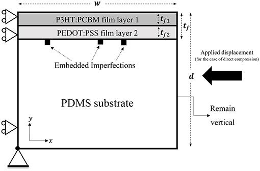
Figure 2. The bilayer film-substrate system and boundary conditions used for the numerical simulations. (Note that for the case of indirect compression, a tensile displacement is applied in the z-direction).
The simulations were performed under the displacement-controlled condition with two different loading scenarios: “direct compression” (applied displacement in x-direction, as shown in Figures 1A, 2) and “indirect compression” through applied tensile deformation in z-direction (shown in Figure 1B). For the case of direct compression, two different numerical models of plane strain and generalized plane strain are considered in this study. Note that the theoretical formulas introduced in section Theory Overview are under the premise of plane strain. Generalized plane strain is a more general and realistic 2D model which takes into account the 3D effects (by incorporating the uniform out-of-plane displacement). The indirect compression simulations were carried out using only the generalized plane strain model due to the nature of this deformation mode.
The finite element software package ABAQUS (Version 2017, Dassault Systems Simulia Corp., Johnston, RI, USA) was employed for the modeling using eight-noded quadrilateral continuum elements throughout the entire model. Uniform element distribution is applied for the film layers (with at least four layers of elements along the thickness direction of each film). A graded element distribution, with the element size increasing gradually from top to bottom, is considered for the substrate. The problem dimensions are w = d = 1, 000 μm with the total film thickness tf = 0.1 μm; note that this is essentially a semi-infinite size for the substrate. In the case of generalized plane strain, a z-direction thickness needs to be defined and it is taken as unity. The thicknesses of the upper and lower films are represented by, respectively, tf1 and tf2. The two film thicknesses are systematically varied in this work to study its effects on surface wrinkling. The fractional volume ratio of the upper film layer (tf1/tf) is considered as a reference measure when presenting the results in the following sections. All materials in the models are taken to be isotropic linear-elastic. The upper film layer is P3HT:PCBM (a conjugated polymer blend of regioregular poly-3-hexylthiophene and phenyl-C61-butyric acid methyl ester) with Young's modulus of Ef1 = 7, 300 MPa; the lower film layer is PEDOT:PSS (poly-3,4-ethylenedioxythiophene and polystyrene sulfonate acid) with Young's modulus of Ef2 = 2, 000 MPa (Lang et al., 2009). Poisson's ratio of νf = 0.35 is assumed for both film layers. For the compliant PDMS (polydimethylsiloxane) substrate, Es = 2.97 MPa (Tahk et al., 2009) and νs = 0.495; the Poisson's ratio is defined slightly smaller than 0.5 to avoid potential convergence problems. Note that this combination of layered films and substrate is the same as those reported for flexible organic solar cells (Kaltenbrunner et al., 2012) as well as a part of the mechano-optoelectronic composite structure being developed as flexible strain sensors (Ryu and Mongare, 2018).
The pre-existing material defects [referred to as the embedded imperfections (Nikravesh et al., 2019)] are incorporated into the numerical model as shown in Figure 2. The defects are regular finite elements in the substrate immediately below the film/substrate interface. Unless otherwise stated, the imperfections carry the material properties of the lower film material and they are distributed in a way to generate the uniform sinusoidal wave form when wrinkling is triggered. The interface remains perfectly bonded. A systematic study of the effects of imperfection distribution and properties are presented in section Effects of Embedded Imperfections.
A brief presentation on model verification and mesh convergence, using the single-layer film model, is first given in section Model Verification. Section Bilayer Composite Films then reports the main simulation results and associated discussion on bilayer composite films.
A large number of simulations were performed to assess the mesh-independency and reliability of the numerical solutions presented in this study. Here, only a subset of the analyses is presented using two single-layer film systems (P3HT:PCBM film on PDMS substrate, and PEDOT:PSS film on PDMS substrate), each with a film thickness of 0.1 μm. The embedded imperfections, being regular finite elements immediately underneath the interface but carrying the film properties, are uniformly distributed, and the imperfection spacing is kept within the valid range for triggering uniform wrinkles as discussed separately in detail in section Effects of Imperfection Distribution. Figure 3A shows the simulated wrinkling wavelength as a function of the number of elements per unit model width for the two cases of film materials, under direct compression using generalized plane strain. Theoretical values based on Equation (1) are also included in the figure for comparison. It is evident that, with sufficiently fine mesh, the numerical solutions converge to theoretical values.
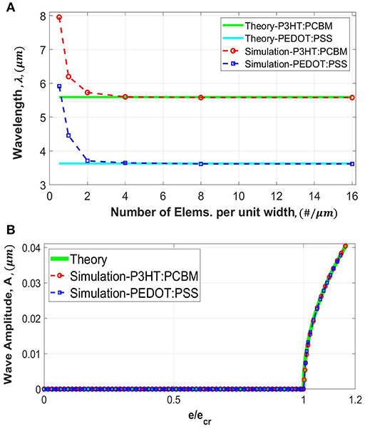
Figure 3. Convergence study for a single-layer film-substrate system, using continuum eight-noded quad elements, for the cases of generalized plane strain under direct compression. Results from two different film materials of P3HT:PCBM and PEDOT:PSS are included. (A) Variation of the simulated wrinkling wavelength with the number of elements per unit width. (B) Variation of the simulated wrinkling amplitude with applied strain normalized by the critical strain (). Theoretical values are also included for comparison.
Figure 3B shows the simulated amplitude as a function of applied compressive strain normalized by the critical buckling strain. The simulations are based on the finest mesh considered in Figure 3A. The theoretical response, given by Equation (3), is also included for comparison (it is independent of the film material). The amplitude remains to be zero until the onset of instability at the critical strain. Once instability starts the sinusoidal wave form takes shape with an increasing amplitude. It is clear that the numerical prediction captures the theoretical response extremely well. Note that the present numerical technique does not require a two-step process with special treatments as in many others; the instability and subsequent evolution of wrinkles can be obtained in a straightforward and seamless manner.
In our previous analysis using four-noded linear elements, mesh convergence can be reached but the converged solution deviated from the theoretical value slightly (Nikravesh et al., 2019). In the present case of eight-noded quadrilateral elements, an excellent agreement between numerical and theoretical solutions is obtained. In the present paper all numerical results are based on the finest mesh (16 eight-noded elements per unit width). Aside from the generalized plane strain results presented here, it is verified from our preliminary simulations that the solutions of all other modeling scenarios (plane strain, bilayer composite films etc.) also showed convergence using the same number of elements per unit width as in Figure 3. We have also found that, in the case of a single-layer film, placing only two layers of uniformly distributed elements (eight-noded quadrilateral) over the film thickness is sufficient to generate the fully converged solutions. As for the case of bilayer composite films, using at least three layers of uniformly distributed elements through each film thickness will yield satisfactory results.
A comprehensive study on the effects of various fractional volumes of film layers on the wrinkle formation is now presented. The fractional volume percentage of the film layers are systematically varied, which is designated as the volume (thickness) percentage of the upper P3HT:PCBM film. For example, 0% P3HT:PCBM means a single-layer of 0.1 μm-thick PEDOT:PSS film, and 50% P3HT:PCBM means a 0.05 μm-thick P3HT:PCBM film on top of a 0.05 μm-thick PEDOT:PSS film. As an illustration, typical forms of numerically simulated sinusoidal wrinkles near one of the randomly chosen embedded imperfections are shown in Figure 4.
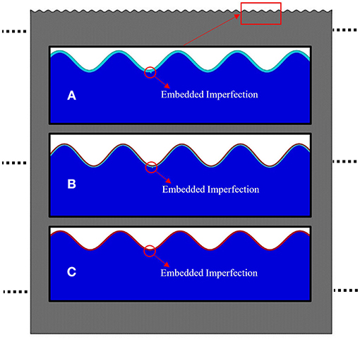
Figure 4. Typical forms of the simulated sinusoidal wrinkles for the cases of (A) 0% P3HT:PCBM, (B) 50% P3HT:PCBM, and (C) 100% P3HT:PCBM. Note that all the images are magnified and scaled for better visualization so the horizontal and vertical length scales are different.
Figure 5A shows the numerically predicted wrinkling wavelength normalized by the initial total film thickness, , as a function of the fractional volume percentage of P3HT:PCBM film from 0 to 100%. The left and right ends thus correspond to the cases of single-layer PEDOT:PSS film and single-layer P3HT:PCBM film, respectively. The results of all the three numerical models of generalized plane strain (GPE) under direct compression and indirect compression, and plane strain (PE) under direct compression, are included in the figure. Also included in Figure 5A are the theoretical values based on Equation (6), as well as the simplistic theoretical approach using the rule-of-mixtures composite tensile modulus Et (Equation 4) in place of Ef in Equation (1). Note that the numerical wavelength values are measured at the onset of bifurcation () for a fair comparison with the existing theories. It can be seen that the numerical predictions generally agree with the theoretical solutions throughout the entire range of volume percentage. Indirect compression (tensile stretching along z-direction) leads to slightly smaller wavelengths than direct compression, because tensile strain leads to a slight reduction in film thickness which, according to Equation (6), scales with the wavelength. From Figure 5A it is apparent that the simplistic rule-of-mixtures approximation does not provide a good wavelength prediction for bilayer films.
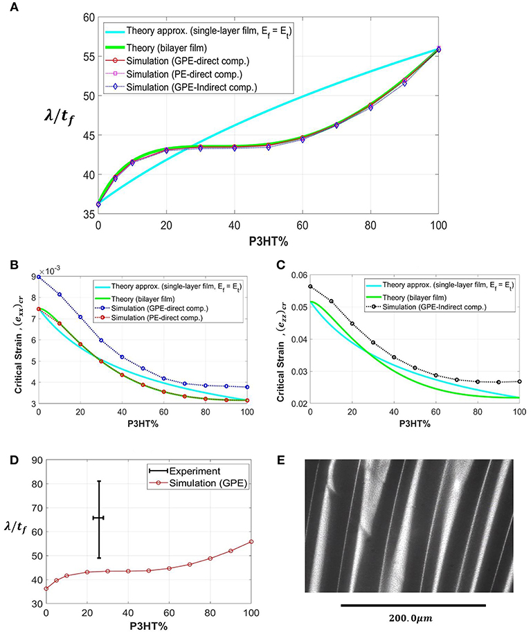
Figure 5. (A) Variation of the simulated wrinkling wavelength normalized by film's total thickness (λ/tf), with the fractional volume percentage of the P3HT:PCBM film, for the cases of generalized plane strain (GPE) direct compression, plane strain (PE) direct compression, and indirect compression (GPE). The theoretical solutions are also included for comparison. (B,C) Variations of the simulated critical buckling strain with the fractional volume percentage of P3HT:PCBM film, for the cases of (B) direct compression and (C) indirect compression. The theoretical solutions are also included. (D) Comparison of an experimentally measured range of wavelengths and numerical predictions. (E) An optical microscopic image showing the surface wrinkles of a bilayer system of P3HT:PCBM/PEDOT:PSS films on the PDMS substrate.
Figure 5B shows the variation of critical compressive strain with the fractional volume percentage of P3HT:PCBM film, under direct compression with the generalized plane strain (GPE) and plane strain (PE) conditions. The theoretical values, based on Equation (7) as well as the simplified approximation, are also shown. The plane-strain numerical result matches the theory (which was derived based on the plane strain condition). The more realistic generalized plane strain model, however, results in greater critical strain values. The relaxation of z-direction constraint allowed in GPE (i.e., allowing Poisson expansion in z when compressed in x) prolongs the regular compressive response, thus increasing the critical strain for instability. Figure 5C shows the comparison for the case of indirect compression using the critical strain definition of Equation (9). Note that by default plane strain is invalid in this case. The comparisons in Figures 5B,C illustrate the limitation of the theory—while the theoretical wavelength solution is accurate (Figure 5A), determination of the critical wrinkling strain necessitates the employment of numerical modeling using the realistic generalized plane strain condition.
An attempt was made to compare the numerical prediction with experiment, using the P3HT:PCBM/PEDOT:PSS bilayer films on a PDMS substrate. Rectangular substrates of length 75 mm and width 12.5 mm were cut from the casted and cross-linked PDMS disk. They were then pre-stretched to >1% tensile strain and fixed onto a glass slide with paper clips. The PDMS substrate was spin-coated with pre-processed PEDOT:PSS and then P3HT:PCBM thin films. Detailed fabrication procedures can be seen in Ryu and Mongare (2018). Upon releasing the pre-strain, the films were under compression and wrinkles can be observed. Due to the non-uniformity of film thickness and the possible uneven in-plane pre-tension, a single wavelength value for the wrinkles was difficult to obtain in a given specimen. Here we plotted the range of measured wavelengths along with the numerical prediction in Figure 5D. A typical optical microscopic image of the surface wrinkles is shown in Figure 5E. In the experiment, the thickness of the P3HT:PCBM layer ranges from 0.200 to 0.230 μm, and the PEDOT:PSS layer ranges from 0.587 to 0.662 μm; the total thickness of the bilayer thus varies from 0.787 to 0.892 μm. The volume fraction of P3HT:PCBM is then calculated within the range of 22–29% (shown in Figure 5D with a bounded horizontal line). The wavelength is measured, from a series of optical images, to be within the range of 44–72 μm. These values were normalized by the maximum total film thickness and plotted with a bounded vertical line in Figure 5D. As can be seen, the numerical result falls outside the range of experimental measurements. It is noted, from the analytical relations given in section Theory Overview, that the wavelength not only depends on the individual film thicknesses but is also sensitive to elastic moduli and their ratios. With the drastically different modulus values of the films and the substrate, any deviation of input parameters used in modeling from the actual material properties can potentially generate a significant difference in wavelength prediction. In Figure 5D, the simulated and experimental wavelengths are within a factor of two.
In addition to wavelength and critical strain, attention is now turned to the wrinkling amplitude. The evolution of the wave amplitude is monitored from numerical simulations for each composite film considered. Figure 6 shows the variation of the amplitude (normalized by the initial total film thickness tf) with the applied compressive strain (normalized by the critical strain ecr), in the case of direct compression under plane strain. A total of 12 volume percentages of the composite films are included, along with the theoretical response based on a single-layer film (Equation 3). (The theoretical solution for bilayer films, Equation (8), will be discussed later in Figure 9). Figure 6 shows that the present numerical approach can simulate wrinkle formation for bilayer films in a straightforward manner as in the case of single-layer film (Figure 3). Amplitudes for most of the composite films deviate from the single-layer solution. The inset in Figure 6 quantifies the deviation when the applied strain is at 1.10 in the post-buckling regime. The horizontal line in the inset denotes the theoretical single-layer solution. It can be seen that, at the single-layer extremes (0 and 100% P3HT:PCBM) numerical predictions generally agree with the single-layer solution. For composite films with P3HT:PCBM contents smaller and larger than about 30%, the simulated amplitudes are, respectively, higher and lower than the single-layer solution.
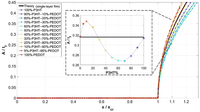
Figure 6. Variations of simulated wrinkling amplitude, normalized by total thickness of the film (A/tf), with the progression of normalized applied compressive strain (), for different fractional volume percentages of the composite films, for the case of plane strain (PE) under direct compression. Note that the amplitudes shown in the inset pertain to .
A similar plot as in Figure 6, but for the case of generalized plane strain under direct compression, is shown in Figure 7. The development of amplitude follows the same trend. Again, when the volume fraction of P3HT:PCBM is below about 30%, the numerically predicted amplitude is greater than the theoretical single-layer solution. The opposite is true when the volume fraction is above about 30%. This deviation cannot be captured by the single-layer theory (Equation 3) since the composite film effect was ignored. A similar amplitude result for the case of indirect compression is shown in Figure 8.
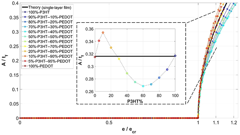
Figure 7. Variations of simulated wrinkling amplitude, normalized by total thickness of the film (A/tf), with the progression of normalized applied compressive strain (), for different fractional volume percentages of the composite films, for the case of generalized plane strain (GPE) under direct compression. Note that the amplitudes shown in the inset pertain to .
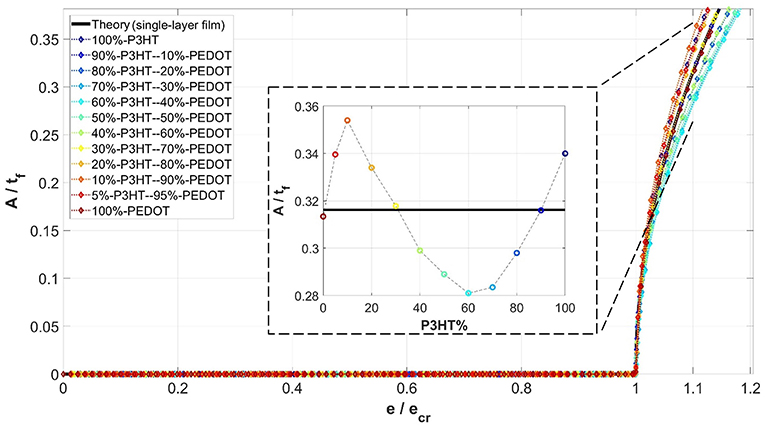
Figure 8. Variations of simulated wrinkling amplitude, normalized by total thickness of the film (A/tf), with the progression of normalized applied strain (), for different fractional volume percentages of the composite films, for the case of generalized plane strain (GPE) under indirect compression. Note that the amplitudes shown in the inset pertain to .
To compare the numerical predictions with the theoretical amplitudes accounting for the composite effect, results from all three modeling scenarios (PE direct compression, GPE direct compression, and GPE indirect compression) are plotted in Figure 9 along with the theoretical solutions for a single-layer film (Equation 3) and for the bilayer composite films (Equation 8), when . It is observed that, unlike the single-layer theory, the bilayer theory is able to capture the variation of amplitude with the volume fraction. The agreement between the numerical results (specifically PE direct compression and GPE direct compression) and Equation (8) is quite well. As for the case of GPE indirect compression, the amplitude follows the same trend but there is lesser agreement with the rest of the cases. We attribute this quantitative inconsistency to the different nature of indirect compression—to attain the same compressive strain in x-direction in the film the structure needs to be pulled in z quite extensively. The change in film thickness due to the Poisson effect may influence the amplitude to a greater extent.
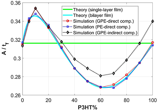
Figure 9. Variations of simulated amplitudes (normalized by the total film thickness) with the fractional volume percentage of P3HT:PCBM layer, for the cases of generalized plane strain (GPE) under direct compression, plane strain (PE) under direct compression, and generalized plane strain (GPE) under indirect compression. Note that the numerical results pertain to in all cases. The theoretical values (both single-layer and bilayer theories) are also included for comparison.
The numerical results presented in section Simulation Results and Discussion were all based on distributions of the embedded imperfections such that uniform wrinkles conforming to the theoretical solutions can be triggered once the critical strain is reached. In the analyses below (section Effects of Imperfection Distribution) we aim to define this “objective” range of imperfection distribution, as well as to illustrate more complex surface instability patterns when the imperfection distribution deviates from the identified range. In section Effects of Imperfection Properties, attention is first devoted to the effect of material properties carried by the imperfections.
As schematically shown in Figure 2, the imperfections were placed in the substrate immediately below the lower film. The material properties of the lower film were used in these imperfection elements. One may interpret this arrangement as having an imperfect interface with occasional geometric irregularities, which is physically plausible. On the other hand, if properties different from those of the film material are used for the imperfections, the interface may be considered as bearing occasional contaminations (which is likely the rule rather than the exception in actual materials). Here, we numerically investigate the sensitivity of wrinkle formation to imperfection properties used in the model.
The model with 50% P3HT:PCBM is utilized (i.e., equal thickness of P3HT:PCBM and PEDOT:PSS films), with the elastic modulus of the imperfections, Eimp, varied from 50 to 73,000 MPa. Direct compression under generalized plane strain is considered. Two sets of simulations were carried out using different Poisson's ratios for the imperfections (νimp), one with 0.495 (equal to that of the substrate) and the other with 0.35 (equal to that of the two film materials). Figures 10A,B show the evolutions of normalized wrinkle amplitude as the applied compressive strain increases (the applied strain is normalized by the critical value), for the case of νimp = 0.495 and 0.35, respectively. It is evident that the present embedded imperfection approach shows very good repeatability—the amplitude response remains unchanged over a wide span of imperfection modulus. Only when Eimp becomes much smaller than the film modulus does deviation start to show. In addition, comparing Figure 10A with Figure 10B the imperfection Poisson's ratio plays essentially no role in affecting wrinkling behavior for the two Poisson's ratios considered. It can be concluded that, in terms of material properties used for the imperfections, there is a high degree of generality using the current methodology.
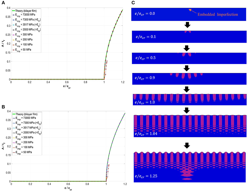
Figure 10. (A,B) Variations of simulated wrinkling amplitude normalized by the total film thickness (A/tf), with the increase in directly applied compressive strain, exx, for the composite film with a fractional volume percentage of 50% under generalized plane strain. (A) νimp = 0.495, and (B) νimp = 0.35. (C) Development of the surface wrinkles in the vicinity of a typical embedded imperfection, and the variation of the stress contours, σyy, near the imperfection. Note that the pink color shows the tensile regions and the blue color shows the compressive and zero stress regions. Note that all the images are magnified to various deformation scales for better visualization.
With the current approach, surface instability was initially triggered in the vicinity of the embedded imperfections. Upon further straining, the perturbation propagates throughout the entire film surface. Such phenomenon is associated with the disturbance of the stress fields near the imperfection. As an example, a typical form of the formation and progression of the wrinkles near an embedded imperfection is shown in Figure 10C (including the two-color σyy stress contours) for the case of 50% P3HT:PCBM bilayer film. Note that, for clarity purposes, only the tensile (pink color) and compressive (blue color) regions are visually shown here in Figure 10C. As can be seen, from the very beginning of the simulation, the stress disturbance can be recognized near the embedded imperfection at the early stages of deformation. Upon reaching the critical strain, , localized wrinkles around the imperfection location can be discerned. Further deformation leads to uniform wrinkles throughout the entire surface. The wrinkle amplitude continues to increase with the applied compression.
In this section, the effects of various imperfection placements on the wrinkle formation are investigated. From our extensive preliminary simulations it was found that, to trigger surface instability, defining only one imperfection immediately below the film-substrate interface will be sufficient. However, the induced wrinkling pattern may change depending on the imperfection distribution.
Consider now the three models under direct compression in generalized plane strain with the following film materials: 100% PEDOT:PSS single-layer film, 50% PEDOT:PSS−50% P3HT:PCBM composite film, and 100% P3HT:PCBM single-layer film. In the case of uniform imperfection distributions, the spacing between adjacent imperfections, Simp, was systematically varied (or equivalently, the total number of imperfections distributed uniformly within the constant model width of 1,000 μm was varied). The simulated wavelength, λ, as a function of the imperfection spacing Simp for the three material models are shown in Figure 11A. As can be seen, for a wide range of imperfection spacing, the simulated wrinkling wavelength tends to remain invariant. This stable value of wavelength is expressed as λs (different for the three film materials). Note that the numerically predicted λs also converges to the theoretical value expressed by Equation (6) as illustrated in section Bilayer Composite Films. The wavelengths of the three materials obtained in Figure 11A can be normalized by their respective λs and plotted against the normalized imperfection spacing Simp/λs, as presented in Figure 11B. It is evident that the range of imperfection spacing which generates the constant wavelength coincides for the three models, attesting to the generality of the current approach. The imperfection spacing can be divided into three regions I, II, and III as labeled in Figure 11B. Region II (10 ≤ Simp/λs ≤ 55) is associated with the stable wavelength (), in which the wrinkling wavelength is invariant with respect to the imperfection distribution. The wrinkling configuration within this region is sinusoidal and uniform throughout the model width, a typical case of which is shown in Figure 11D.
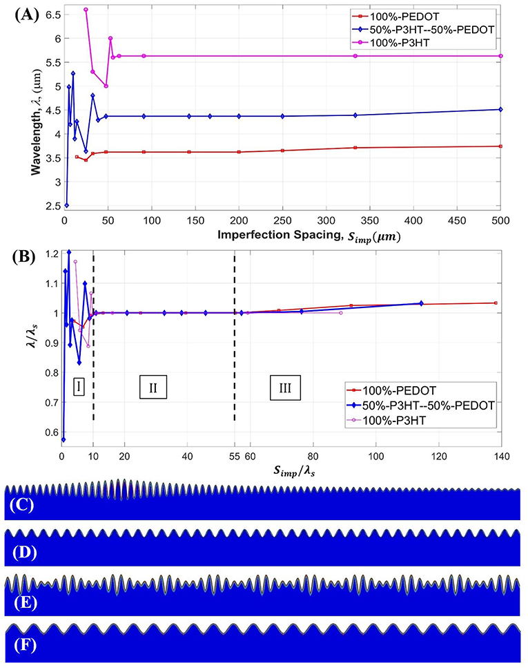
Figure 11. (A) Variation of the wrinkle wavelength, λ, with the uniform imperfection spacing, Simp. (B) The curves in (A) normalized by the value of stable wavelength, λs. (C–F) Typical wrinkling configurations obtained from the simulations for various uniform imperfection distributions, for the models with a bilayer film. (C) Non-uniform/localized wave pattern corresponding to region III in (B). (D) Fully sinusoidal wave form independent of the imperfection distribution () corresponding to region II in (B). (E,F) Complex wave patterns as the imperfection spacing becoming smaller () corresponding to region I in (B). Note that in (F) the uniform sinusoidal wave is fully controlled by the very dense imperfections (). Various displacement scaling factors were used in (C–F) for better visualization, and the images cover only a portion of the surface region.
In regions I and III defined in Figure 11B, the value deviates from unity, and the resulting wrinkle pattern may become qualitatively different from the ideal theoretical form. In region III, where Simp/λs> 55, the imperfection density is very low. Instability emerges locally at the imperfection site and the wrinkles did not spread uniformly over the model width. An example is shown in Figure 11C. In the cases of very high imperfection densities (region I, with Simp/λs < 10), various uneven periodic wavy forms can be obtained such as in Figure 11E. Figure 11F is another example when Simp/λs ≤ 1.0, in which a sinusoidal wave with the wavelength artificially controlled by the imperfection spacing was observed.
Aside from the uniform imperfection distributions presented above, another comprehensive set of simulations were carried out involving random imperfection distributions. Only the main findings are reported here. Depending on the maximum and minimum values of the imperfection spacing, Simp, in a given model, the wrinkle pattern can be uniform or non-uniform. The uniform sinusoidal waveform, converging to the theoretical solutions, can only be generated when both the conditions 10 ≤ (Simp)max/λs ≤ 55 and 10 ≤ (Simp)min/λs ≤ 55 are met. These conditions correlate well with the range identified in the case of uniform imperfection distributions (region II in Figure 11B). For random imperfection distributions with the maximum or minimum Simp beyond the specified range, the wrinkle pattern will deviate from the theoretical form and can become non-uniform and complex, with the actual configuration dictated by the placement of imperfections. The present results, based on higher-order finite elements, are generally consistent with those obtained previously using linear elements (Nikravesh et al., 2019), with the upper limit of the Simp/λs ratio remaining at 55 and the lower limit being 10 instead of 6.
Another feature worthy of note is the possible edge effects when the imperfection density is very high. Consider the model of 50% PEDOT:PSS−50% P3HT:PCBM composite film with a uniform imperfection distribution. A typical pattern obtained for the entire width of the problem is shown in Figure 12 for the case of 10 ≤ Simp/λs ≤ 55. The uniform wrinkles near the edge (Figure 12A) and in the middle section of the model domain (Figure 12B) are exactly the same. Figure 13 shows a representative case with a very high imperfection density, Simp/λs <10. It is evident that the wrinkling form near the model edge (Figure 13A) is very different from that in the middle section (Figure 13B), with both showing non-uniform patterns. The edge effects observed here can potentially appear in the actual film-substrate system, depending on the nature of the pre-existing interfacial defects. The results shown here serve to illustrate the robustness of the present numerical approach in prediction spatial variations of the wrinkles.
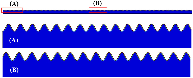
Figure 12. Typical wrinkling configurations on the entire surface region, obtained from the simulations for the models with a bilayer film, and with the imperfection distributions satisfying the condition of . (A) Magnified portion of the film near the edge. (B) Magnified portion of the film in the middle section.
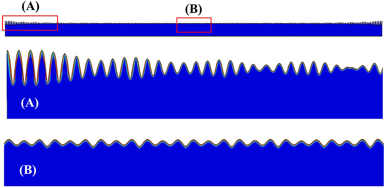
Figure 13. Typical wrinkling configurations on the entire surface region, obtained from the simulations for the models with a bilayer film, and with a very high imperfection density . (A) Magnified portion of the film near the edge. (B) Magnified portion of the film in the middle section.
The embedded imperfection approach considered in this study may be readily applied to multilayer composite films. For proof of feasibility we present here examples involving 2–5 layers of thin films above the same PDMS substrate, under direct compression in generalized plane strain. The placement of film layers and their associated material properties are listed in Table 1. For all the film layers, the same Poisson's ratio of 0.35 is chosen. The total film thickness is kept constant at 0.1 μm in all the simulations, with equal fractional volumes (identical thicknesses) for the film layers. The imperfection density is kept within the valid range for uniform wrinkles once instability commences.
In all four cases, uniform wrinkling can be successfully simulated once the critical strain is reached, with a typical result shown in Figure 14A. Figures 14B–E show the localized views of the wrinkles for the cases of 2, 3, 4, and 5 film layers, respectively, when the applied compressive strain . The colors represent the σxx stress contours. It can be seen that the composite film layers are under significant compressive stresses while the stress magnitudes in the PDMS substrate are much smaller. In the “valley” region, the top film layer (with the highest modulus) experiences the greatest compression while the stresses in the lower layers are less compressive. On the other hand, the top layer in the “peak” region is not the most compressive because the local bending-induced tensile strain is superimposed on the overall compressive strain. In all cases, stress discontinuities across the interfaces can be observed. The results illustrate that the present numerical approach is able to predict surface instability and the evolution of wrinkles, in a straightforward manner, for structures containing multilayer composite films.
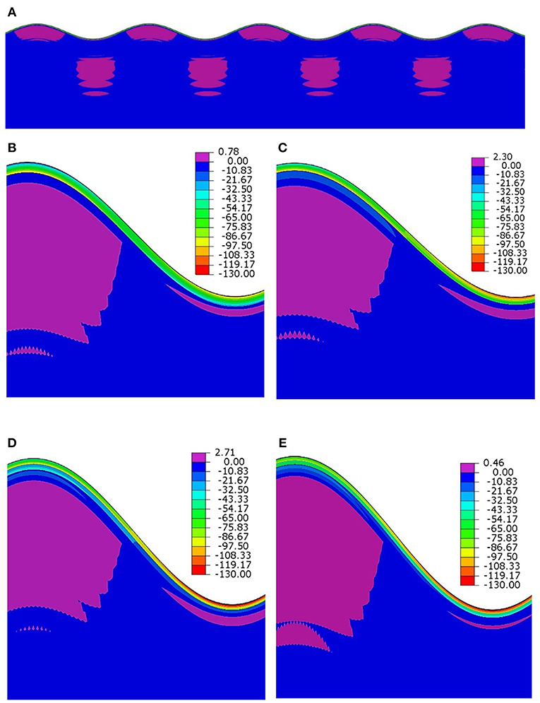
Figure 14. Deformed configurations and contour plots of σxx (MPa) in the vicinity of the surface wrinkles, corresponding to 1.10 in all cases. (Deformations in all the images are magnified for better visualization). (A) Typical wrinkling configuration and stress distribution, (B) two-layer composite film, (C) three-layer composite film, (D) four-layer composite film, (E) five-layer composite film.
A comprehensive numerical study was conducted for simulating surface instability in the form of wrinkles (buckles), when a thin-film material is attached to a thick compliant substrate. Attention is devoted to composite thin films with more than one film layer, using a finite element-based approach with embedded imperfections at the film-substrate interface. When the film is subject to compression, by compressing the structure directly or pulling the structure in the transverse direction leading to indirect film compression, wrinkling can be triggered once the compressive strain reaches a critical value. Using an organic optoelectronic structure consisting of P3HT:PCBM and PEDOT:PSS thin films atop a thick PDMS substrate as the model system, deformation from the pre-buckling to post-buckling stages can be numerically modeled in a straightforward manner without any further special treatment. Throughout the entire range of fractional volume (thickness) ratio of the two constituent films, the wrinkling wavelength, critical strain, and amplitude under plane-strain compression predicted by the modeling agree well with available theoretical solutions. The theory, however, under-predicts the critical strain for instability because it cannot account for the realistic generalized plane strain behavior, so the numerical technique will have to be relied upon. When the imperfection density is outside of a certain range, the numerical model predicts special forms of non-uniform wrinkles which cannot be captured by the theory. The present numerical approach is also shown to be able simulate wrinkling in the cases of composite films containing more than two layers.
All datasets generated for this study are included in the manuscript.
SN and Y-LS conceived the idea for the research and contributed writing the first draft. SN performed the numerical simulations directed by Y-LS. DR directed the sample fabrication and experimental measurements. All authors collaborated on finalizing the manuscript.
The author(s) disclosed receipt of the following financial support for the research, authorship, and/or publication of this article. The authors would like to acknowledge NASA EPSCoR CAN (grant #: 80NSSC17M0050), New Mexico Space Grant Consortium, and NASA's Space Grant College, and Fellowship Program for supporting this study.
The authors declare that the research was conducted in the absence of any commercial or financial relationships that could be construed as a potential conflict of interest.
Bayat, A., and Gordaninejad, F. (2015). Switching band-gaps of a phononic crystal slab by surface instability. Smart Mater. Struct. 24:075009. doi: 10.1088/0964-1726/24/7/075009
Bush, K. A., Rolston, N., Gold-Parker, A., Manzoor, S., Hausele, J., Yu, Z. J., et al. (2018). Controlling thin-film stress and wrinkling during perovskite film formation. ACS Energy Lett. 3, 1225–1232. doi: 10.1021/acsenergylett.8b00544
Cao, Y., and Hutchinson, J. W. (2012a). From wrinkles to creases in elastomers: the instability and imperfection-sensitivity of wrinkling. Proc. R. Soc. A 468, 94–115. doi: 10.1098/rspa.2011.0384
Cao, Y., and Hutchinson, J. W. (2012b). Wrinkling phenomena in neo-Hookean film/substrate bilayers. J. Appl. Mech. 79:031019. doi: 10.1115/1.4005960
Cao, Y.-P., Zheng, X.-P., Jia, F., and Feng, X.-Q. (2012). Wrinkling and creasing of a compressed elastoplastic film resting on a soft substrate. Comput. Mater. Sci. 57, 111–117. doi: 10.1016/j.commatsci.2011.02.038
Chung, J. Y., Nolte, A. J., and Stafford, C. M. (2011). Surface wrinkling: a versatile platform for measuring thin-film properties. Adv. Mater. 23, 349–368. doi: 10.1002/adma.201001759
De Tommasi, D., Puglisi, G., and Zurlo, G. (2014). Failure modes in electroactive polymer thin films with elastic electrodes. J. Phys. D 47:065502. doi: 10.1088/0022-3727/47/6/065502
Groenewold, J. (2001). Wrinkling of plates coupled with soft elastic media. Phys. A Stat. Mech. Appl. 298, 32–45. doi: 10.1016/S0378-4371(01)00209-6
Hsieh, Y.-T., Chen, J.-Y., Shih, C.-C., Chueh, C.-C., and Chen, W.-C. (2018). Mechanically robust, stretchable organic solar cells via buckle-on-elastomer strategy. Org. Electr. 53, 339–345. doi: 10.1016/j.orgel.2017.12.011
Huang, R., Stafford, C. M., and Vogt, B. D. (2007). Effect of surface properties on wrinkling of ultrathin films. J. Aerospace Eng. 20, 38–44. doi: 10.1061/(ASCE)0893-1321(2007)20:1(38)
Huck, W. T., Bowden, N., Onck, P., Pardoen, T., Hutchinson, J. W., and Whitesides, G. M. (2000). Ordering of spontaneously formed buckles on planar surfaces. Langmuir 16, 3497–3501. doi: 10.1021/la991302l
Hutchinson, J. W. (2013). The role of nonlinear substrate elasticity in the wrinkling of thin films. Philos. Trans. R. Soc. A. 371:20120422. doi: 10.1098/rsta.2012.0422
Ji, Q., Zhang, C., Qi, X., Li, R., Hu, X., Guo, L. J., et al. (2018). Enhancing the efficiencies of organic photovoltaic and organic light-emitting diode devices by regular nano-wrinkle patterns. J. Shanghai Jiaotong Univ. 23, 45–51. doi: 10.1007/s12204-018-1908-y
Jia, F., Cao, Y.-P., Liu, T.-S., Jiang, Y., Feng, X.-Q., and Yu, S.-W. (2012). Wrinkling of a bilayer resting on a soft substrate under in-plane compression. Philos. Mag. 92, 1554–1568. doi: 10.1080/14786435.2011.652691
Kaltenbrunner, M., White, M. S., Głowacki, E. D., Sekitani, T., Someya, T., Sariciftci, N. S., et al. (2012). Ultrathin and lightweight organic solar cells with high flexibility. Nat. Commun. 3:770. doi: 10.1038/ncomms1772
Kim, J. B., Kim, P., Pégard, N. C., Oh, S. J., Kagan, C. R., Fleischer, J. W., et al. (2012). Wrinkles and deep folds as photonic structures in photovoltaics. Nat. Photon. 6:327. doi: 10.1038/nphoton.2012.70
Lang, U., Naujoks, N., and Dual, J. (2009). Mechanical characterization of PEDOT: PSS thin films. Synth. Metals 159, 473–479. doi: 10.1016/j.synthmet.2008.11.005
Lejeune, E., Javili, A., and Linder, C. (2016). An algorithmic approach to multi-layer wrinkling. Extr. Mech. Lett. 7, 10–17. doi: 10.1016/j.eml.2016.02.008
Lipomi, D. J., Tee, B. C. K., Vosgueritchian, M., and Bao, Z. (2011). Stretchable organic solar cells. Adv. Mater. 23, 1771–1775. doi: 10.1002/adma.201004426
Mei, H., Landis, C. M., and Huang, R. (2011). Concomitant wrinkling and buckle-delamination of elastic thin films on compliant substrates. Mech. Mater. 43, 627–642. doi: 10.1016/j.mechmat.2011.08.003
Nikravesh, S., Ryu, D., and Shen, Y.-L. (2019). Direct numerical simulation of buckling instability of thin films on a compliant substrate. Adv. Mech. Eng. 11:1687814019840470. doi: 10.1177/1687814019840470
Nolte, A. J., Cohen, R. E., and Rubner, M. F. (2006). A two-plate buckling technique for thin film modulus measurements: applications to polyelectrolyte multilayers. Macromolecules 39, 4841–4847. doi: 10.1021/ma0606298
Ram, S. K., Desta, D., Rizzoli, R., Falcão, B. P., Eriksen, E. H., Bellettato, M., et al. (2017). Efficient light-trapping with quasi-periodic uniaxial nanowrinkles for thin-film silicon solar cells. Nano Energy 35, 341–349. doi: 10.1016/j.nanoen.2017.04.016
Ryu, D., and Mongare, A. (2018). Corrugated photoactive thin films for flexible strain sensor. Materials 11:1970. doi: 10.3390/ma11101970
Saha, S. K. (2017). Sensitivity of the mode locking phenomenon to geometric imperfections during wrinkling of supported thin films. Int. J. Solids Struct. 109, 166–179. doi: 10.1016/j.ijsolstr.2017.01.018
Schauer, S., Schmager, R., Hünig, R., Ding, K., Paetzold, U. W., Lemmer, U., et al. (2018). Disordered diffraction gratings tailored by shape-memory based wrinkling and their application to photovoltaics. Opt. Mater. Express 8, 184–198. doi: 10.1364/OME.8.000184
Shen, Y.-L. (2010). Constrained Deformation of Materials: Devices, Heterogeneous Structures and Thermo-Mechanical Modeling. New York, NY: Springer Science and Business Media.
Stafford, C. M., Guo, S., Harrison, C., and Chiang, M. Y. (2005). Combinatorial and high-throughput measurements of the modulus of thin polymer films. Rev. Sci. Instr. 76:062207. doi: 10.1063/1.1906085
Tahk, D., Lee, H. H., and Khang, D.-Y. (2009). Elastic moduli of organic electronic materials by the buckling method. Macromolecules 42, 7079–7083. doi: 10.1021/ma900137k
Volynskii, A., Bazhenov, S., Lebedeva, O., and Bakeev, N. (2000). Mechanical buckling instability of thin coatings deposited on soft polymer substrates. J. Mater. Sci. 35, 547–554. doi: 10.1023/A:1004707906821
Wang, B., Bao, S., Vinnikova, S., Ghanta, P., and Wang, S. (2017). Buckling analysis in stretchable electronics. NPJ Flex. Electr. 1:5. doi: 10.1038/s41528-017-0004-y
Wang, C., Zhang, H., Yang, F., Fan, Y., and Liu, Q. (2017). Enhanced light scattering effect of wrinkled transparent conductive ITO thin film. RSC Adv. 7, 25483–25487. doi: 10.1039/C7RA02726E
Wang, Y., Li, Z., and Xiao, J. (2016). Stretchable thin film materials: fabrication, application, and mechanics. J. Electr. Packag. 138:020801. doi: 10.1115/1.4032984
Zhang, Y., Zheng, J., Fang, C., Li, Z., Zhao, X., Li, Y., et al. (2018). Enhancement of silicon-wafer solar cell efficiency with low-cost wrinkle antireflection coating of polydimethylsiloxane. Solar Energy Mater Solar Cells 181, 15–20. doi: 10.1016/j.solmat.2017.10.004
Zheng, X.-P., Cao, Y.-P., Li, B., Feng, X.-Q., and Yu, S.-W. (2010). Surface wrinkling of nanostructured thin films on a compliant substrate. Comput. Mater. Sci. 49, 767–772. doi: 10.1016/j.commatsci.2010.06.020
Zhu, J., Kollosche, M., Lu, T., Kofod, G., and Suo, Z. (2012). Two types of transitions to wrinkles in dielectric elastomers. Soft Matter 8, 8840–8846. doi: 10.1039/c2sm26034d
Keywords: buckling, wrinkling, thin film, finite element analysis, instability, composite, imperfection
Citation: Nikravesh S, Ryu D and Shen Y-L (2019) Surface Instability of Composite Thin Films on Compliant Substrates: Direct Simulation Approach. Front. Mater. 6:214. doi: 10.3389/fmats.2019.00214
Received: 05 May 2019; Accepted: 19 August 2019;
Published: 04 September 2019.
Edited by:
Fernando Fraternali, University of Salerno, ItalyReviewed by:
Yong Ni, University of Science and Technology of China, ChinaCopyright © 2019 Nikravesh, Ryu and Shen. This is an open-access article distributed under the terms of the Creative Commons Attribution License (CC BY). The use, distribution or reproduction in other forums is permitted, provided the original author(s) and the copyright owner(s) are credited and that the original publication in this journal is cited, in accordance with accepted academic practice. No use, distribution or reproduction is permitted which does not comply with these terms.
*Correspondence: Yu-Lin Shen, c2hlbnlsQHVubS5lZHU=
Disclaimer: All claims expressed in this article are solely those of the authors and do not necessarily represent those of their affiliated organizations, or those of the publisher, the editors and the reviewers. Any product that may be evaluated in this article or claim that may be made by its manufacturer is not guaranteed or endorsed by the publisher.
Research integrity at Frontiers

Learn more about the work of our research integrity team to safeguard the quality of each article we publish.