 Pawan Boonyoung1
 Takatoshi Kasukabe2
 Yasuto Hoshikawa2
 Ángel Berenguer-Murcia3,4
 Diego Cazorla-Amorós3,4Bundet Boekfa5Hirotomo Nishihara2Takashi Kyotani2
 Khanin Nueangnoraj1*
- 1School of Bio-Chemical Engineering and Technology, Sirindhorn International Institute of Technology, Thammasat University – Rangsit Campus, Pathum Thani, Thailand
- 2Institute of Multidisciplinary Research for Advanced Materials, Tohoku University, Sendai, Japan
- 3Materials Institute, University of Alicante, Alicante, Spain
- 4Department of Inorganic Chemistry, University of Alicante, Alicante, Spain
- 5Department of Chemistry, Faculty of Liberal Arts and Science, Kasetsart University, Kamphaeng Saen Campus, Nakhin Pathom, Thailand
Schwarzites have a three-dimensional sp2 carbon structure with negative Gaussian curvatures. They can be synthesized through the deposition of carbon by chemical vapor deposition on a zeolite template and may be formed by increasing the amount of carbon. In this research, the amount of carbon deposition was increased by shortening the length of the diffusion pathways of the template through the use of nano-sized zeolite Y (nano-FAU). It was found that significantly larger quantities of carbon could be deposited inside the pores of nano-FAU (40 nm), compared to the micro-sized zeolite Y (300 nm). It is thus confirmed that by shortening the diffusion pathways enables more carbon to infiltrate into the center of the template before the pore channels are blocked, which leads to larger carbon depositions. A low acetylene gas concentration (15% vol in N2) and a prolonged period for chemical vapor deposition (6 h) is preferable for effectively loading carbon into the template. The obtained carbon replica exhibits the ordered structure derived from zeolite Y with an unprecedented 72 carbon atoms per supercage, of which a model with a structure similar to schwarzite was proposed.
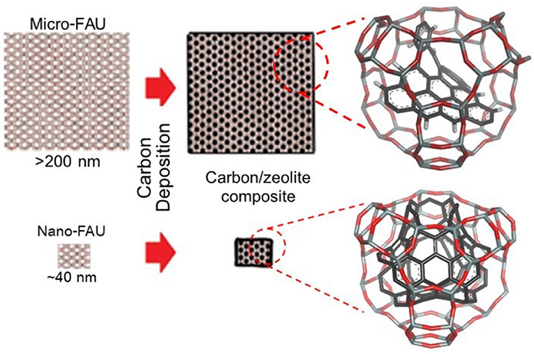
Graphical Abstract. Possible formation of schwarzites by carbon loading inside the “nano-FAU” in comparison to that loaded inside the “micro-FAU”.
Introduction
The primal unit of sp2 carbon, graphene, is a highly versatile material that serves as the base structure of a variety of carbon architectures, such as fullerene (Kroto et al., 1985) and carbon nanotubes (Iijima, 1991). Researchers have shown that the induction of negative Gaussian curvature (Mackay, 1985) onto graphene forms a carbon structure with an open topology (Mackay and Terrones, 1991). This structure enables the construction of a three-dimensional framework, also known as schwarzite (Phillips et al., 1992; Vanderbilt and Tersoff, 1992).
It has been recently reported that the growth of carbon inside the hard porous materials, so-called template carbonization (Kyotani et al., 1997), has successfully synthesized carbons with structures that fits the description of schwarzites (Braun et al., 2018). Zeolite Y (FAU) is a commonly used template material, due to its three-dimensional pore structure, high thermal stability, and large pores (Kyotani et al., 2003; Braun et al., 2018). Conventionally, carbon is loaded into FAU through the use of chemical vapor deposition (CVD) with a carbon-source gas, such as acetylene (Hou et al., 2005) or propylene (Ma et al., 2000), as illustrated in Figure 1A. The carbon prepared from FAU and other zeolites is also known as zeolite-templated carbon (ZTC). Thus far, these materials have shown great potential in energy storage applications (Nishihara and Kyotani, 2012), such as electrochemical capacitors and hydrogen storages, due to their inherently high surface area (Ma et al., 2001) and high electrical conductivity (Lee et al., 2017).
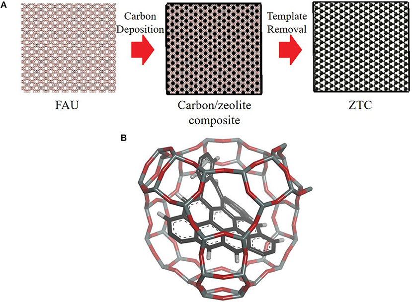
Figure 1. (A) Illustration of chemical vapor deposition on the FAU and (B) structural model of the ZTC embedded inside one supercage of FAU, obtained by CVD method on the micro-FAU (Nishihara et al., 2018). Note that the gray and red sticks represent the FAU framework, whereas the black sticks are for the carbons.
Schwarzites can be formed by increasing the amount of carbon. It has been reported that a low amount of carbon was deposited in FAU (Ma et al., 2000, 2002), which can lead to the carbon structure not fully resembling the pore morphology of FAU [one of which is shown in Figure 1B (Nishihara et al., 2018)]. During CVD, the carbon that was deposited inside the template could reduce the size of pore openings, preventing more carbon from infiltrating into the center of the template. Furthermore, carbon deposition on the external surface of FAU can also lead to the formation of graphitic stacking layers (Yang et al., 2006; Nueangnoraj et al., 2013; Choi et al., 2015), which further exacerbates the inability of carbon to enter the template. The deposition of a larger quantity of carbon inside the FAU template would allow the formation of schwarzites.
There have been numerous attempts to increase the amount of carbon deposition inside FAU. The most notables include the use of a pressure-pulsed CVD (P-CVD) (Nueangnoraj et al., 2013) and doping the zeolite template with catalytic ions such as calcium (Kim et al., 2017) and lanthanum (Kim et al., 2016). P-CVD yielded a carbon structure with approximately 63 carbon atoms per supercage of FAU. However, it was observed that a thick layer of graphitic carbon was grown on the external surface of FAU crystals, which caused pore blockages and prevented the deposition of carbon inside the template. In contrast, the introduction of catalytic ions into the FAU framework allowed CVD to be performed at lower temperatures. The lower temperature with catalysis allows the carbon-source gas to crack primarily inside the template. This inhibits the deposition of carbon on the external surface of FAU, and therefore, reduces the formation of graphitic stacking. It was reported that ~80% of the pore channels in La3+ catalyzed FAU could be filled with carbon from CVD.
Apart from the methods previously mentioned, there is another parameter affecting the carbon deposition: the diffusion pathway. During CVD, carbon-source gas must diffuse into the pore channels of the template where deposition takes place. This may cause a layer of graphitic carbon to grow near or on the external surface of the zeolite. Therefore, the internal pores of the zeolite get blocked by already-deposited carbon, making it difficult for carbon to diffuse through the pores. Reducing the size of the FAU template proportionately shortens the length of the diffusion pathways, which would allow a greater portion of pore channels to be occupied before carbon is unable to infiltrate into the zeolite. To the best of our knowledge, there has been no investigation of the effects on the carbon deposition from the size of the FAU template. Therefore, in this work, we attempt to use a “nano-FAU” (<100 nm particles) for the deposition of carbon, so-called a “nano-templating” method, toward the formation of carbon schwarzites (Graphical Abstract).
Experimental
Preparation of Zeolite Y
Zeolite Y (FAU) was prepared from an aluminosilicate gel with a molar composition of 2.4 (TMA)2O: 0.024 Na2O: Al2O3: 3.4 SiO2: 370 H2O, using a slightly modified method reported elsewhere (Morales-Pacheco et al., 2009). The gel was prepared by dissolving sodium hydroxide pellets (Wako Pure Chemical Industries, Ltd.), tetramethylammonium hydroxide pentahydrate (TMAOH·5H2O, Wako Pure Chemical Industries, Ltd.), and aluminum isopropoxide (Wako Pure Chemical Industries, Ltd.) in RO water. Tetraethyl orthosilicate (Wako Pure Chemical Industries, Ltd.) was then added dropwise to the clear solution under vigorous stirring. The solution was then left to age for 20 h at room temperature.
The gel was hydrothermally treated in a PTFE vessel within a stainless-steel autoclave at 90 or 130°C for 120 h to crystallize the FAU particles. At the hydrothermal temperature of 90°C, the obtained FAU had an average size of 40 nm, while 300 nm particles were obtained at 130°C. After the hydrothermal treatment, the FAU suspension was immediately centrifuged (41,000 RCF for 30 min at 5°C) and re-dispersed in RO water at least three times to remove alkalinity. Finally, the sample was dried at 105°C, overnight.
Template Carbonization
FAU (0.50 g) was placed into a vertical quartz reactor and heated to 600°C under N2 flow (150 ml·min−1) at a heating rate of 5°C·min−1. Continuous chemical vapor deposition (C-CVD) was conducted on the zeolite by acetylene flow in N2 (150 ml·min−1) at 600°C. The concentration of acetylene was varied from 15% vol to 35% vol in N2, and the CVD period was varied from 2 to 6 h. After CVD, the carbon/zeolite composite was heated to 900°C at 5°C·min−1 under 150 ml·min−1 of N2, and the heat treatment was performed for another 3 h. The samples are referred to as ZTC40-xx-yy and ZTC300-xx-yy, where xx and yy are the acetylene concentration (% vol in N2) and CVD time (h), respectively. The obtained carbon/zeolite composite was then washed with hydrofluoric acid (46 wt% HF, Wako Pure Chemical Industries, Ltd.) to remove the template.
Characterizations
The structure of the as-prepared FAU was confirmed using X-ray diffraction (Rigaku Miniflex 600), with a CuKα source (40 kV and 15 mA). Laser diffraction (Microtrac MT3300EXLL) and SEM (Hitachi S4800) were used to estimate the particle size distribution of the obtained zeolite crystals.
The carbon content of the carbon/zeolite composites was obtained from thermogravimetric analysis (Shimadzu TGA-51) by combusting the samples in air at 800°C with a heating rate of 5°C·min−1. The quantity of ordered carbon was estimated by differentiating the TG data of the liberated carbon, which was combusted in 5% vol O2 in N2 at 800°C with a heating rate of 2°C·min−1.
TEM (JEOL JEM-2010) and XRD were employed to confirm the successful replication of FAU pores by the deposited carbon.
Modeling of Carbon
The models of the carbon were generated using the programs Avogadro and Chem3D 17.1. The Merck Molecular Force Field (MMFF94) was employed for the energy minimization of the developed structure. After that, the semi-empirical algorithm PM6 was used in collaboration with the program MOPAC2016 for the final geometrical optimization. Avogadro and GaussView 5.0 were employed to calculate the energy of the predicted carbon structure.
Results and Discussions
One of the main challenges in preparing the ZTC by CVD on the zeolite is the low carbon deposition inside the template. To increase the amount of carbon deposition, the following approaches were considered:
• Nano-sized FAU particles (40 nm, or nano-FAU) as the template material are used to reduce the length of the diffusion pathways, so that larger amounts of carbon could infiltrate into the center before blockages occur. Micro-sized FAU (>200 nm, or micro-FAU) are used for comparison.
• Acetylene is used as the carbon-source gas due to its small size relative to ethylene and propylene, which would allow for easy diffusion into the template.
Preparation of the Zeolite Template
Once the hydrothermal treatment of the aluminosilicate gel was completed, the FAU crystals were obtained as a white suspension within the gel. Centrifugation and re-dispersion were performed to remove alkalinity from the zeolite. XRD patterns of the obtained crystals were compared with a reference FAU sample (HSZ320NAA, Tosoh Corporation), which confirmed the successful synthesis of FAU particles. Laser diffraction was used to estimate the average particle size of the FAU, which was 40 nm for those hydrothermally treated at 90°C, while the 130°C treated crystals were ~300 nm (see Supplementary Material for details).
Formation of Zeolite-Templated Carbon
The various stages of ZTC formation, which are the FAU particles, carbon/zeolite composites, and liberated ZTC, are shown in Figure 2. It can be seen from Figures 2A,D that the FAU particles have approximate sizes of 40 and 150–300 nm, respectively, which are in good agreement with the laser diffraction analysis. After CVD, it is observed that there is little change in the size and morphology of the crystals (Figures 2B,E). This suggests that carbon is only deposited onto the zeolite. Finally, after the zeolite template was removed by HF washing (Figures 2C,F), the particles of carbon retain their cubic shape, indicating that there was no collapse of the structure.
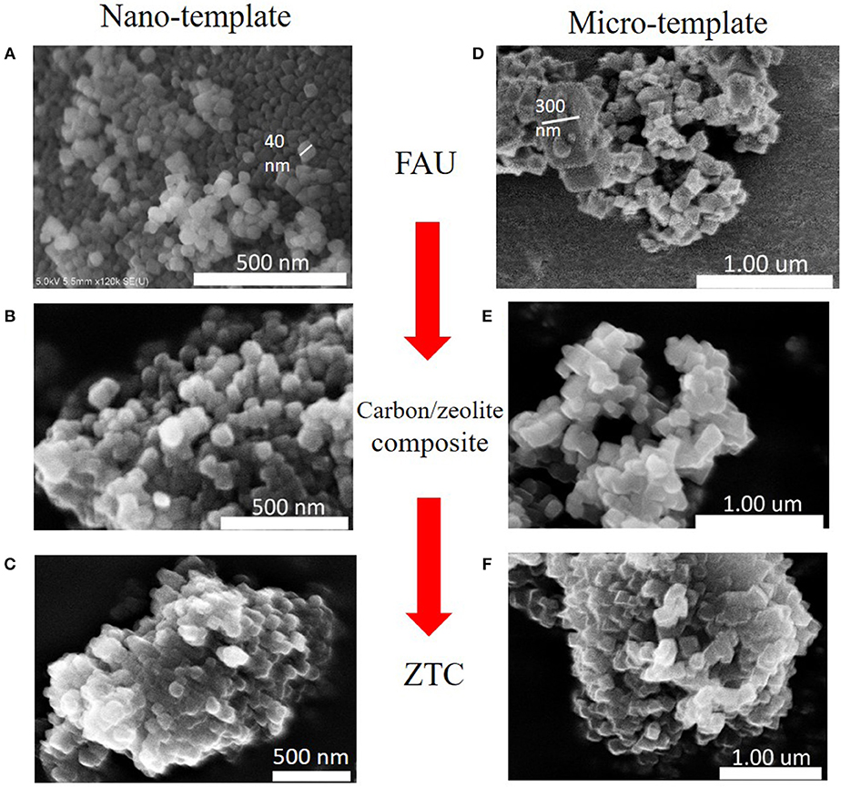
Figure 2. SEM images of the various stages of ZTC preparation; (A) 40 nm FAU (nano-FAU), (B) carbon/nano-FAU composite, (C) liberated ZTC40, (D) 300 nm FAU (micro-FAU), (E) carbon/micro-FAU composite, and (F) liberated ZTC300.
Confirmation of the Template Replication
XRD patterns (Figure 3) of the liberated carbon display a prominent sharp peak at 2θ = 6.3°, which is at the identical angle of diffraction as found in the FAU. This corresponds to the (111) plane and is calculated to have a d-spacing of 1.4 nm in accordance with Bragg's Law. This supports the claim that carbon has replicated the morphology of the pores in FAU. A small secondary peak could be observed at 2θ = 18° in most of the samples. This peak signifies the presence of polyfluoroethylene (PTFE), which likely contaminated the sample during the washing process due to the use of PTFE vessels and filtration membranes. Nevertheless, PTFE is not important in this work and may be neglected.
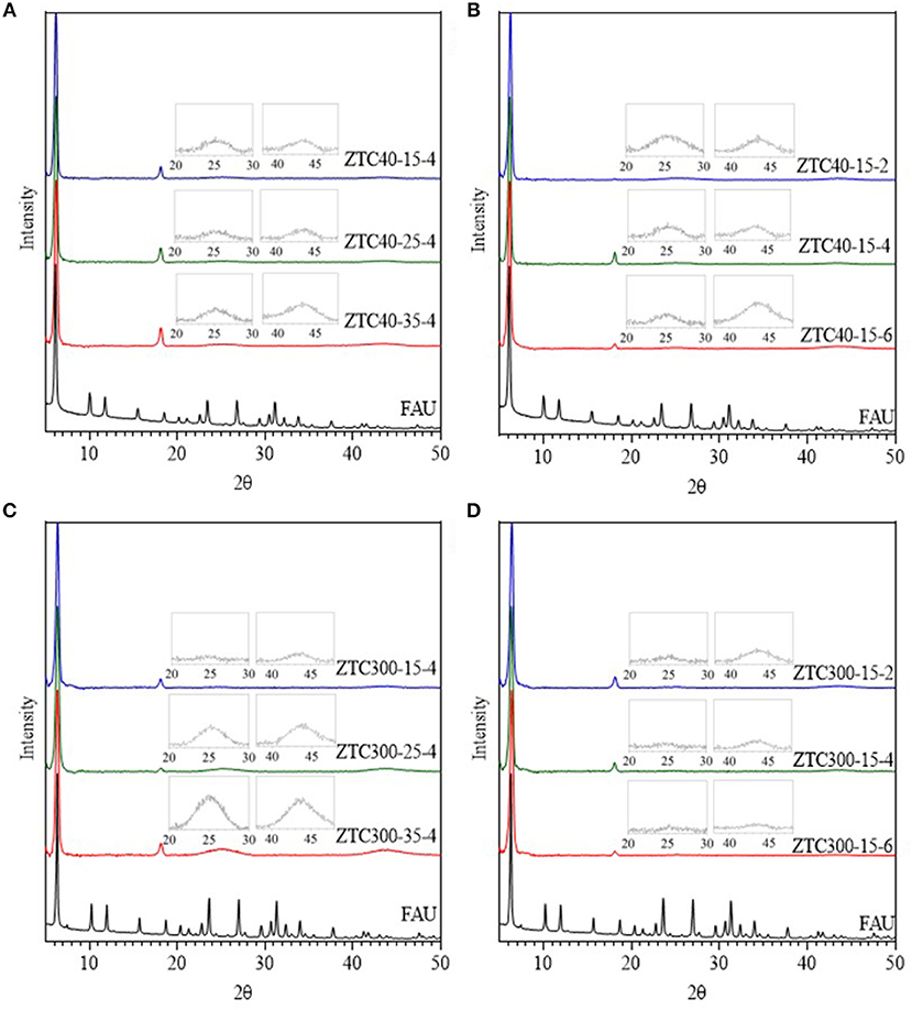
Figure 3. XRD patterns of the liberated carbon at various (A) acetylene concentrations and (B) CVD times for ZTC40, and at various (C) acetylene concentrations and (D) CVD times for ZTC300.
The XRD patterns of ZTC300-25-4 and ZTC300-35-4 in Figure 3C show two distinct broad peaks at approximately 2θ = 26° and 2θ = 44°, which are not present in the FAU. These correspond to the (002) and (10) planes in the graphitic carbon, having a d-spacing of 0.34 and 0.21 nm, respectively. When the XRD plots were magnified, these peaks become visible in all ZTC samples. Interestingly, when the acetylene concentration was increased, the intensity of the (002) and (10) planes become more prominent for ZTC produced from 300 nm FAU. However, this effect is diminished when the 40 nm template was used. Therefore, a higher acetylene concentration greatly favors the formation of a graphitic structure on the surface of larger-sized FAUs, which should be avoided as this would cause pore blockage.
TEM images of the liberated carbon display black lines with high uniformity, as shown in Figure 4. The periodicity of these ordered lines is ~1.3 nm, which is similar to the d-spacing in FAU and is in good agreement with the XRD patterns of the liberated carbon. Therefore, it is confirmed that the carbon has successfully replicated the FAU pore structures.
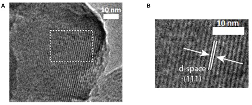
Figure 4. (A) TEM images of ZTC40 showing the periodicity of the ordered carbon and (B) magnification of the dashed white box.
Carbon Content
Carbon Content of the Carbon/Zeolite Composite
Carbon contents in the carbon/zeolite composites were estimated from the thermogravimetric (TG) curves and are listed in Table 1. At the lowest acetylene concentration (15% in N2), carbon/zeolite composites produced from 40 nm FAU have a higher carbon content for all CVD times, compared to those prepared from 300 nm FAU. The ZTC prepared from both sizes of FAU exhibited an increase in carbon content as the CVD time was prolonged from 2 to 6 h. This suggests that the carbon could be consistently deposited into the template. However, as the acetylene concentration increases, only ZTC300 exhibits a large increase in carbon deposition, from 0.56 to 1.02 g·g−1, whereas ZTC40 increases from 0.72 to 0.75 g·g−1, which is comparatively small. The 300 nm FAU is, therefore, significantly more susceptible to increases of acetylene concentration. We discuss in detail the formation of different types of carbon after the CVD in the following section.
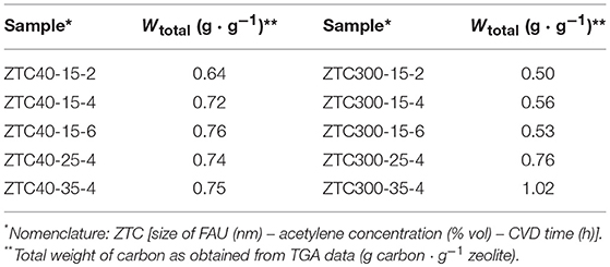
Table 1. Total carbon content of the carbon/zeolite composites.
Quantification of the Ordered Carbon
As the XRD patterns of the carbon replicas indicate the presence of a graphitic structure in addition to an ordered carbon structure, the samples need to be quantified to distinguish such structures. We had previously reported (Nueangnoraj et al., 2013) that these carbons combust at relatively different temperatures, ca. 560°C for the ordered carbon, and at a higher temperature for the stacked graphitic layers. Therefore, differential thermogravimetric (DTG) analysis was applied to estimate the quantity of each carbon structure.
The DTG plots were obtained by differentiating the TG curves of the liberated carbon. A peak fitting program, Fityk (Wojdyr, 2010), was employed to distinguish and separate the two peaks observed (Figure 5). The Gaussian and Pearson VII equations were used to fit the first (ordered carbon) and the second (graphitic carbon) peaks, respectively, and to estimate the area under the curves. However, for samples ZTC300-25-4 and ZTC300-35-4, the asymmetric Gaussian and asymmetric Pearson VII equations showed a better fit. The quantity of ordered carbon (Winside) for each ZTC sample was calculated and is listed in Table 2.
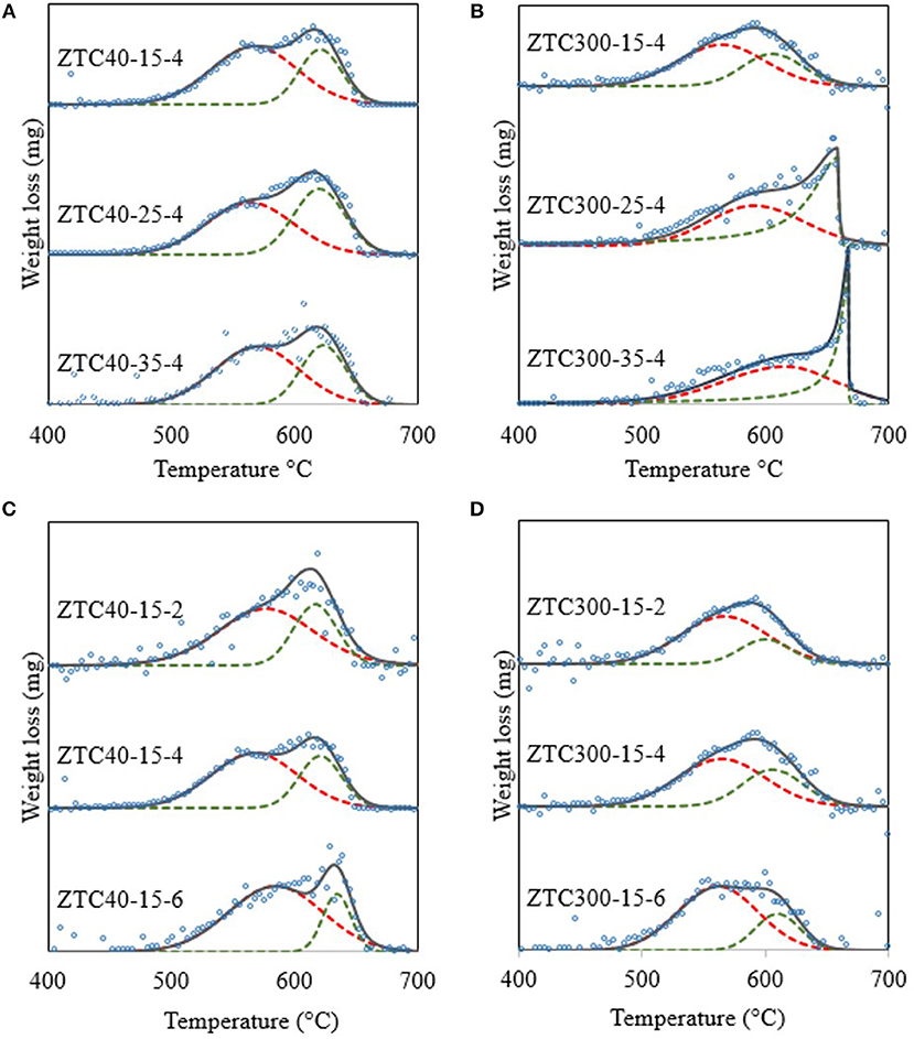
Figure 5. DTG plots and peak fittings for the difference in acetylene concentration on (A) ZTC40 (B) ZTC300, and the difference in CVD time for (C) ZTC40 and (D) ZTC300. Open circles show the raw differentiated TG data. Dashed lines represent the peak fittings while the solid lines are the summation of the peak fittings.
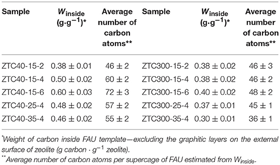
Table 2. Carbon content that deposited inside the FAU template and the average number of carbon atoms per supercage.
It is observed that Winside of ZTC40 (prepared from 40 nm FAU) is higher than that of ZTC300 for most of the CVD conditions, except for a CVD time of 2 h, where the carbon contents are equivalent. This supports the hypothesis that short diffusion pathways enable more carbon to easily deposit deep within the template.
Prolonged CVD time is favorable for the deposition of carbon inside both sizes of the FAU, in particular, the nano-FAU. The increase in Winside for ZTC40 as the CVD time was prolonged from 2 to 6 h was 0.22 g·g−1, whereas the increase for ZTC300 was only 0.02 g·g−1. Therefore, a longer CVD time is preferable for the deposition of a larger amount of carbon inside the template. However, we have found that the steady-state has been reached with a CVD time of 12 h (see Supplementary Material), and Winside increased to 0.62 g·g−1.
A high acetylene concentration, in contrast, has a detrimental effect on the carbon loading. Winside for both ZTC40 and ZTC300 decrease as the source-gas concentration was increased. A possible explanation for this phenomenon is as follows. When the source gas concentration increases, carbon would be deposited near the pore entrance or on the external surface of the zeolite. As described earlier, the internal pores of the zeolite would get blocked by already-deposited carbon, making it difficult for carbon to diffuse through the pores. The excess carbon is therefore deposited onto the external surface of FAU, leading to the formation of graphitic stacking layers. This is far more significant for ZTC300 than ZTC40, as the increase in external carbon deposition is from 0.18 to 0.72 g·g−1. For ZTC40, the graphite content increases from 0.22 to 0.29 g·g−1, which was calculated by subtracting Winside from the total carbon content. This result is further supported by the XRD patterns shown in Figure 3, as the broad (002) and (10) peaks indicate the presence of large quantities of graphitic structures for ZTC300 at high acetylene concentrations.
A low acetylene concentration with a long CVD time is therefore preferable for a large amount of carbon deposition inside the FAU. ZTC40-15-6 shows the highest Winside of 0.60 g·g−1, which corresponds to approximately 72 carbon atoms per supercage of FAU (Table 2). This carbon content is competitive to that of the P-CVD method for commercial FAU (particle size >200 nm), where the quantity of carbon deposited inside the template was ~63 atoms per supercage of FAU. However, this “nano-templating” approach is simpler in practice due to the use of continuous CVD, as opposed to the pulse and vacuum approach of the P-CVD.
Molecular Structure of the Carbon
The hypothetical model for ZTC40-15-6 was drawn using Avogadro with the Merck Molecular Force Field (MMFF94) for energy minimization (Halgren, 1996a,b). The ZTC model was constructed with the following assumptions:
• The model should be able to fit inside the pores of FAU.
• The model is constructed of only carbon hexagons and heptagons.
• The deposition of carbon is fully uniform throughout the template.
Based on the experiment, one supercage of the FAU would contain 72 carbon atoms. We thus assemble these atoms in accordance with the above assumptions, as shown in Figure 6A. The one-unit structure of this model (C72, Figure 6B) is fitted inside the supercage of FAU and is connected to another 4 units to form the three-dimensional framework. The carbon model was then geometrically optimized with the semi-empirical algorithm PM6 (Stewart, 2007, 2008) using the MOPAC2016 (Stewart, 2016). There are other possibilities to form the models based on the arrangement of polygons (see Supplementary Material). However, we proposed the most geometrically stable model as displayed in Figure 6. It should be noted that the structure shown in Figure 6 is built as an average structure. Each unit structure of the real ZTC material is actually diverse and ZTC cannot be defined as a crystal, because its XRD pattern does not show many peaks (Figure 3). The atomic coordinates of the average structure shown in Figure 6 can be found in Supplementary Material.
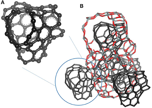
Figure 6. The proposed model of (A) single C72 unit and (B) the framework of C72 units connected in a tetrahedral configuration that is embedded inside the FAU framework. Note that the gray and red sticks represent the FAU template, whereas the black sticks are for the carbons.
Due to the pore structure of FAU and the presence of carbon heptagons, the model resembles a tetrapod and can form the three-dimensional tetrahedral framework as described earlier. This model fits the description of schwarzites proposed by Braun et al. (2018), and thus, could be one type of schwarzite.
Conclusion
Zeolite-templated carbon (ZTC) was successfully synthesized in both 40 and 300 nm FAU. Carbon could be effectively deposited inside the smaller “nano-FAU” rather than the “micro-FAU” because of the shorter diffusion pathways. A longer CVD time is beneficial for the deposition of carbon inside the template. Higher acetylene concentrations during the CVD inhibit the diffusion of carbon inside the FAU and favor the growth of graphitic layers on the external surface of the template. ZTC-40-15-6, which was prepared by using the nano-FAU with the lowest CVD concentration (15% vol in N2) and longest CVD time (6 h), possesses the largest amount of carbon deposition inside the template (0.60 g·g−1). This corresponds to 72 carbon atoms per supercage of FAU, one of the highest to date. A structural model of this carbon was proposed, which can be considered as one type of schwarzite. Furthermore, the amount of carbon deposition is competitive with that of previous studies, such as P-CVD (63 atoms). The “nano-templating” approach is simpler to perform due to the use of continuous CVD. It is possible for the other forms of carbon schwarzites to be synthesized through further refinement of this “nano-templating” approach. This approach can also be combined with other carbon deposition techniques, which could open many possibilities for a new branch of research on novel templated carbon materials.
Author Contributions
PB, ÁB-M, DC-A, HN, TKy, and KN contributed conception and design of the study. PB, TKa, and YH performed the experiments. HN, TKy, and KN analyzed and organized the results. BB contributed in the proposed model. PB wrote the first draft of the manuscript. All authors contributed to manuscript revision, read, and approved the submitted version.
Conflict of Interest Statement
The authors declare that the research was conducted in the absence of any commercial or financial relationships that could be construed as a potential conflict of interest.
Acknowledgments
This work was supported by Grant-in-Aid for Scientific Research (A), 17H01042 (HN); the Nano-Macro Materials, Devices and System Research Alliance; and the Network Joint Research Center for Materials and Devices. The support from Sirindhorn International Institute of Technology under the Excellent Thai Student Program (PB) and from the Research Grant for New Scholar (Grant No. MRG6080153) co-funded by the Thailand Research Fund (TRF); the commission on Higher Education, Thailand; and Thammasat University, are also acknowledged.
Supplementary Material
The Supplementary Material for this article can be found online at: https://www.frontiersin.org/articles/10.3389/fmats.2019.00104/full#supplementary-material
References
Braun, E., Lee, Y., Moosavi, S. M., Barthel, S., Mercado, R., Baburin, I. A., et al. (2018). Generating carbon schwarzites via zeolite-templating. Proc. Natl. Acad. Sci. U.S.A. 115, E8116–E8124. doi: 10.1073/pnas.1805062115
Choi, S., Kim, H., Lee, S., Wang, Y., Ercan, C., Othman, R., et al. (2015). Large-scale synthesis of high-quality zeolite-templated carbons without depositing external carbon layers. Chem. Eng. J. 280, 597–605. doi: 10.1016/j.cej.2015.06.055
Halgren, T. A. (1996a). Merck molecular force field. I. Basis, form, scope, parameterization, and performance of MMFF94. J. Comput. Chem. 17, 490–519. doi: 10.1002/(SICI)1096-987X(199604)17:5/6<490::AID-JCC1>3.0.CO;2-P
Halgren, T. A. (1996b). Merck molecular force field. III. Molecular geometries and vibrational frequencies for MMFF94. J. Comput. Chem. 17, 553–586. doi: 10.1002/(SICI)1096-987X(199604)17:5/6<553::AID-JCC3>3.0.CO;2-T
Hou, P.-X., Yamazaki, T., Orikasa, H., and Kyotani, T. (2005). An easy method for the synthesis of ordered microporous carbons by the template technique. Carbon 43, 2624–2627. doi: 10.1016/j.carbon.2005.05.001
Kim, K., Kwon, Y., Lee, T., Cho, S. J., and Ryoo, R. (2017). Facile large-scale synthesis of three-dimensional graphene-like ordered microporous carbon via ethylene carbonization in CaX zeolite template. Carbon 118, 517–523. doi: 10.1016/j.carbon.2017.03.082
Kim, K., Lee, T., Kwon, Y., Seo, Y., Song, J., Park, J. K., et al. (2016). Lanthanum-catalysed synthesis of microporous 3D graphene-like carbons in a zeolite template. Nature 535, 131–135. doi: 10.1038/nature18284.
Kroto, H. W., Heath, J. R., O'Brien, S. C., Curl, R. F., and Smalley, R. E. (1985). C60: buckminsterfullerene. Nature 318, 162–163.
Kyotani, T., Ma, Z., and Tomita, A. (2003). Template synthesis of novel porous carbons using various types of zeolites. Carbon 41, 1451–1459. doi: 10.1016/S0008-6223(03)00090-3
Kyotani, T., Nagai, T., Inoue, S., and Tomita, A. (1997). Formation of new type of porous carbon by carbonization in zeolite nanochannels. Chem. Mater. 9, 609–615. doi: 10.1021/cm960430h
Lee, H., Kim, K., Kang, S. H., Kwon, Y., Kim, J. H., Kwon, Y. K., et al. (2017). Extremely high electrical conductance of microporous 3D graphene-like zeolite-templated carbon framework. Sci. Rep. 7:11460. doi: 10.1038/s41598-017-11602-5
Ma, Z., Kyotani, T., Liu, Z., Terasaki, O., and Tomita, A. (2001). Very high surface area microporous carbon with a three-dimensional nano-array structure: synthesis and its molecular structure. Chem. Mater. 13, 4413–4415. doi: 10.1021/cm010730l
Ma, Z., Kyotani, T., and Tomita, A. (2000). Preparation of a high surface area microporous carbon having the structural regularity of Y zeolite. Chem. Commun. 23, 2365–2366. doi: 10.1039/B006295M
Ma, Z., Kyotani, T., and Tomita, A. (2002). Synthesis methods for preparing microporous carbons with a structural regularity of zeolite Y. Carbon 40, 2367–2374. doi: 10.1016/S0008-6223(02)00120-3
Mackay, A. L., and Terrones, H. (1991). Diamond from graphite. Nature 352:762. doi: 10.1038/352762a0
Morales-Pacheco, P., Alvarez, F., Bucio, L., and Domínguez, J. M. (2009). Synthesis and structural properties of zeolitic nanocrystals II: FAU-type zeolites. J. Phys. Chem. C 113, 2247–2255. doi: 10.1021/jp8070713
Nishihara, H., Fujimoto, H., Itoi, H., Nomura, K., Tanaka, H., Miyahara, M. T., et al. (2018). Graphene-based ordered framework with a diverse range of carbon polygons formed in zeolite nanochannels. Carbon 129, 854–862. doi: 10.1016/j.carbon.2017.12.055
Nishihara, H., and Kyotani, T. (2012). Templated nanocarbons for energy storage. Adv. Mater. 24, 4473–4498. doi: 10.1002/adma.201201715
Nueangnoraj, K., Nishihara, H., Imai, K., Itoi, H., Ishii, T., Kiguchi, M., et al. (2013). Formation of crosslinked-fullerene-like framework as negative replica of zeolite Y. Carbon 62, 455–464. doi: 10.1016/j.carbon.2013.06.033
Phillips, R., Drabold, D. A., Lenosky, T., Adams, G. B., and Sankey, O. F. (1992). Electronic structure of schwarzite. Phys. Rev. B 46, 1941–1943.
Stewart, J. J. (2007). Optimization of parameters for semiempirical methods V: modification of NDDO approximations and application to 70 elements. J. Mol. Model. 13, 1173–1213. doi: 10.1007/s00894-007-0233-4
Stewart, J. J. (2008). Application of the PM6 method to modeling the solid state. J. Mol. Model. 14:499. doi: 10.1007/s00894-008-0299-7
Vanderbilt, D., and Tersoff, J. (1992). Negative-curvature fullerene analog of C60. Phys. Rev. Lett. 68, 511–513.
Wojdyr, M. (2010). Fityk: a general purpose peak-fitting program. J. Appl. Crystallogr. 43, 1126–1128. doi: 10.1107/S0021889810030499
Keywords: zeolite-templated carbon, zeolite Y, nano-template, chemical vapor deposition, schwarzites
Citation: Boonyoung P, Kasukabe T, Hoshikawa Y, Berenguer-Murci Á, Cazorla-Amorós D, Boekfa B, Nishihara H, Kyotani T and Nueangnoraj K (2019) A Simple “Nano-Templating” Method Using Zeolite Y Toward the Formation of Carbon Schwarzites. Front. Mater. 6:104. doi: 10.3389/fmats.2019.00104
Received: 14 January 2019; Accepted: 23 April 2019;
Published: 16 May 2019.
Edited by:
Federico Cesano, University of Turin, ItalyReviewed by:
Efrem Braun, University of California, Berkeley, United StatesHumberto Terrones, Rensselaer Polytechnic Institute, United States
Copyright © 2019 Boonyoung, Kasukabe, Hoshikawa, Berenguer-Murcia, Cazorla-Amorós, Boekfa, Nishihara, Kyotani and Nueangnoraj. This is an open-access article distributed under the terms of the Creative Commons Attribution License (CC BY). The use, distribution or reproduction in other forums is permitted, provided the original author(s) and the copyright owner(s) are credited and that the original publication in this journal is cited, in accordance with accepted academic practice. No use, distribution or reproduction is permitted which does not comply with these terms.
*Correspondence: Khanin Nueangnoraj, khanin@siit.tu.ac.th