- 1Department of Civil Engineering, Nagoya Institute of Technology (Nitech), Nagoya, Japan
- 2Nippon Koei Co., Ltd., Tokyo, Japan
This study evaluated the performance of a tubular microbial fuel cell (MFC) having a core of air-chamber wrapped with an anion exchange membrane in sewage wastewater treatment. Three MFCs were vertically assembled into one module and floated in sewage water channels before and after treatments in the primary sedimentation tank. The two MFC-modules exhibited nearly similar electricity production in the range of 1.3–5.7 Wh·m−3-MFC while the bottom MFCs (60–90 cm) showed a decrease in electricity compared with the top (0–30 cm) and the middle MFCs (30–60 cm) due to the water leakage into air-cathode. One MFC module was then evaluated for its chemical oxygen demand (COD) removal efficiency with two external resistances of 27 and 3Ω in a chemostat reactor (MFC:reactor = 1:5, v/v) using three hydraulic retention times (HRTs), i.e., 3, 6, and 12 h. The best COD removal efficiency (COD-REMFC), 54 ± 14%, and BOD removal efficiency, 37 ± 17%, were observed with a resistance of 3Ω and a 12 h HRT, which resulted in 3.8 ± 2.0 A·m−3 of current recovery and 15 ± 7.5% of Coulombic efficiency. The electricity generation efficiency (EGEMFC) was the best with a resistance of 27Ω and a 12 h HRT, accounting for 0.19 ± 0.12 kWh·kg-COD−1 with a 17 ± 6.4% COD-REMFC and 0.65 ± 0.10 Wh·m−3 electricity production. Based on calculations using the COD-REMFC and EGEMFC, the integration of MFC treatments prior to aeration can reduce wastewater treatment electricity consumption by 55%.
Introduction
Electricity consumption in sewage wastewater treatment accounts for 1–3% of domestic electricity consumption in developed countries (Maktabifard et al., 2018) while sewage potentially has much more bio-mass energy in itself (Shizas and Bagley, 2004). Anaerobic digestion of sewage sludge has received significant attention to neutralize this energy imbalance (Yan et al., 2017). In Japan, 1.5 × 10¹⁰ m3·yr−1 of sewage water is treated in sewage wastewater treatment plants, which includes ~400 mg·L−1 of chemical oxygen demand (COD). Based on the assumption that all organic carbon is converted to CH4, and, by extension, that all CH4 is converted to electricity, the potential biomass energy in sewage water (PEW) is as much as 2.1 × 10¹⁰ kWh·yr−1 (Supplementary Information). This PEW is ~1.8-fold higher than that of sewage sludge (PES). The PEW of sewage sludge can be calculated as a product of the sewage sludge produced annually (2.2 × 10⁹ kg-dry sludge (DS)·yr−1) and its calorific value (4,500 kcal·kg-DS−1). Theoretically, all electricity requirements for sewage treatment can be met via energy conversion of > 0.67 kWh·kg-COD−1 from sewage water or > 1.8 kWh·kg-DS−1 from sewage sludge. However, biogas production cannot be directly applied to sewage water due to its relatively lower carbon content compared with the carbon content in the same volume of sludge. Therefore, organic matter must be concentrated from sewage water prior to biogas production, which includes concentrations of the membrane bioreactor (Martinez-Sosa et al., 2011), aquatic weeds (Kaur et al., 2018), and algae (Arcila and Buitrón, 2016). An alternative technology that directly recovers energy from sewage water is the microbial fuel cell (MFC) (Liu et al., 2004; Li et al., 2014). The MFC is a promising technology that can be introduced into existing sewage treatment plants without large-scale construction projects.
MFC is a technology collecting the electrons emitted in the microbial oxidation of organic matter to an electrode (Logan et al., 2006). The representative configuration of an MFC includes a single chamber with an anode filled with wastewater, which is equipped with an oxygen-reducing cathode exposed to the atmosphere (Liu et al., 2004; Du et al., 2007). Theoretically, this type of MFC has the best cathodic potential due to the high electrode potential of O2/H2O. Tentatively, three key materials, i.e., an anode, separator, and cathode, determine the performance of the MFCs. Although electrode improvement and optimization is still ongoing (Li et al., 2017), carbon-based anodes, such as carbon brushes and felt (Logan et al., 2007), and cathode supporting carbon-catalysts, such as carbon black and activated carbon (Zhang et al., 2014a,b), are becoming increasingly popular due to their commercial availability and inexpensive cost.
For the application of MFCs in sewage water treatment at a large-scale, separation of air, and liquid phases while retaining the permeability of ions or oxygen is of great concern (Leong et al., 2013). An ion exchange membrane (IEM) (Kim et al., 2007; Leong et al., 2013) and PTFE layer (Cheng et al., 2006) have been used to separate the air and liquid phase, which allow ion and oxygen mobility, respectively. In particular, large-scale MFCs with greater depth favor IEMs, especially the cation exchange membrane (CEM), due to their commercial availability and physical toughness at a relatively inexpensive cost (Ge and He, 2016; Liang et al., 2018). However, the MFC that treats the wastewater contains higher concentrations of various cations, such as Na+, Ca2+, K+, and NH3+, in the anolyte, which compete with protons that attach to the negatively charged function groups in the CEM (Rozendal et al., 2006). This can cause reduction in electricity production after long-term operation (Ge and He, 2016; Liang et al., 2018).
An anion exchange membrane (AEM) is an alternative IEM and involves the movement of OH− from air (cathode) to the sewage water in a single chambered MFC as illustrated in Supplementary Figure 1. Previous studies have shown that the AEM is characterized by improved electricity production in the MFC compared with the CEM in not only a dual chambered MFC (Kim et al., 2007; Fornero et al., 2008) but also in a single chambered MFC (Zhang et al., 2010). However, MFCs that use an AEM have never been evaluated for wastewater treatment over long-term operation, such as over 1 month. These facts motivated us to perform a preliminary evaluation of an MFC using an AEM to remove organic matter and recover electricity from the wastewater. Based on the assumption that OH−, generated by oxygen reduction on the cathode, is the dominant anion in the AEM, its limitation can likely extend the lifetime of the MFC. The MFC used in this study was specially designed to be applicable to the existing sewage treatment tank. The MFC first ran in a sewage water channel for 140–230 days to test its electricity generation and lifetime, after which it was placed in a chemostat reactor to evaluate its ability to reduce organic matter.
Materials and Methods
MFC Configuration
The single MFC used in this study was tubular in shape (ϕ4.0 × 33 cm) with a core of the air chamber (Supplementary Figure 1). The air-core was tubular and made of stainless mesh surrounded by a cathode (4π × 33 cm), separator (4π × 33 cm), and anode (4π × 33 cm) without spacing. The cathode was comprised of a carbon cloth (TOYOBO, Osaka, Japan) painted with a mixture of 1.7 mg·cm−2 activated carbon (Wako, Tokyo, Japan), 1.1 mg·cm−2 of carbon black (Fuel Cell Earth, Woburn, MA, USA), 14 μL·cm−2 of isopropanol, 5.6 μL·cm−2 of 20% Poly (diallyldimethylammonium chloride) solution (SIGMA-ALDRICH, St. Louis, MO, USA), and 5.6 μL·cm−2 of 60% PTFE solution (SIGMA-ALDRICH). An AEM (ASTOM, Tokyo, Japan) was used as the separator while a graphite felt sheet, with a thickness of 0.5 cm, was used as the anode (Yoshida et al., 2016b). To collect electrons, a stainless steel mesh (Clever, Toyohashi, Japan) was used in both electrodes. The anode was immersed in a sewage sludge suspension as described in Yoshida et al. (2016c) prior to operation. Three units were vertically connected and assembled to form one MFC module (Figure 1A).
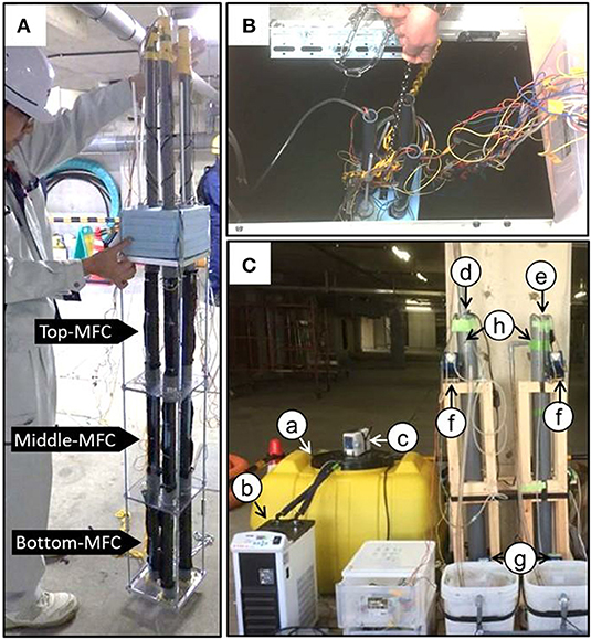
Figure 1. The modularized microbial fuel cells used in this study (A) and the MFC modules floating in the sewage water channel (B) and chemostat reactors (C). In (C), the letters indicate the following components: (a) influent storage tank, (b) cooling water circulating system, (c) impeller for mixing the influent, (d) reactor with the MFC, (e) reactor without the MFC (NON), (f) circulation pump, (g) feeding pump, and (h) effluent outlet. The effluent was sampled from the outlet (h) to determine the COD concentration. The influent was also partially collected from the tube that connected the storage tank (a) to the reactors (d,e).
MFC Operation in Water Channels
Two sets of MFC modules were introduced in water channels for electricity production using the sewage water. The MFC module introduced into the water channel before its treatment in the primary sedimentation tank (PST) was termed IN-MFC while the module introduced into water after the PST-treatment was termed EF-MFC (Figure 1B). The MFC modules were fixed on a steel cage with a styrene foam floater on the top and a plummet at the bottom. The three sets of electrodes in the module were individually polarized with an external resistance of 120 (0–7 days) and 27 Ω (after 7 days). The voltage was measured every hour as described previously (Yoshida et al., 2016b).
Linear Sweep Voltammetry
Linear sweep voltammetry (LSV) of the three MFCs in the IN-MFC module was performed using a potentio-galvanostat analyzer as described as described previously (Yoshida et al., 2016a). The cell current was measured when the anode was connected as the working electrode with the cathode connected to the reference and counter electrodes. When measuring the anodic and cathodic currents, Ag/AgCl (BAS Inc., Tokyo, Japan) was used as the reference electrode. To measure the anodic current, an anode, and cathode were connected as the working and counter electrodes, respectively, while the cathodic current was measured with the cathode as the working electrode and anode as the counter electrode. LSV was performed at a voltage from the open circuit potential to 0 V with a sweep rate of 0.5 mV·s−1.
COD Removal Evaluation by the MFCs
The IN-MFC was removed from the water channel and re-set in a cylindrical chemostat reactor (ϕ7.7 × 130 cm) to evaluate the removal of COD (Nurmiyanto et al., 2017). The approximate volume ratio of MFC:reactor was set to 1:5 (v/v) (Figure 1C). For comparison, a similar cylindrical reactor without an MFC (NON) was also installed in parallel. The reactors were maintained under chemostat conditions to obtain 3, 6, and 12 h hydraulic retention times (HRTs) via a continuous supply of influent from the bottom of the reactor. For the influent, wastewater was taken from a water channel before treatment in the PST. The water was stored in a storage tank with a 300 L capacity, maintained at ~15°C via a cooling water circulation system (AS ONE, Osaka Japan), and mixed continuously using an SMT-101 stirring blade (AS ONE). The temperature of the chemostat reactor was maintained at 30°C with continuous mixing using a magnetic stirrer and circulation via internal wastewater pumping. The three sets of electrodes were individually polarized with an external resistance of 27 and 3Ω. The reactors were maintained under six operational conditions with different combinations of HRTs and external resistances (Supplementary Table 1). The IN-MFC was stabilized under the given operational conditions for at least 12 h prior to the first sampling. The COD and BOD were analyzed for the influent and effluents from the MFC and NON reactors. The analyses were performed at the Environmental Research Center (Nagoya, Japan) as described previously (Goto and Yoshida, 2017). Sampling was repeated at least three times with an interval longer than the HRT under each operational condition.
Results
Electricity Production in the Water Channels
The two MFC modules, i.e., the IN-MFC and EF-MFC, were individually installed and polarized in the water channels for the PST influent and effluent, respectively (Figure 1). In both modules, electricity production drastically increased within 4 days and then became relatively stable (Figure 2). The top and middle MFCs had similar electricity production while the bottom MFC had lower electricity production than the upper MFCs. This trend was observed for both modules.
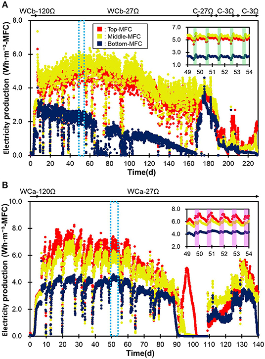
Figure 2. The production of electricity by the three MFCs in the IN-MFC module (A) and EF-MFC module (B). WCb and WCa show the MFCs that were operated in the water channel before and after treatment in the PST, respectively. C indicates the MFCs in a chemostat reactor polarized via resistances of 3 (C-3Ω) and 27Ω (C-27Ω). The green frame represents the morning (5:30–11:30) while the purple frame represents the daytime (8:30–17:30).
In the IN-MFC, the top and middle MFCs were characterized by relatively stable electricity production from days 7–110, with an average of 4.7 ± 0.5 and 5.1 ± 0.6 Wh·m−3-MFC, respectively (Figure 2). The production gradually decreased between days 110 and 130 and then became stable again at 3.4 ± 0.62 Wh·m−3-MFC until the MFC was moved to the chemostat reactor on day 173. Meanwhile, the bottom MFC had a stable electricity production of 2.3 ± 0.33 Wh·m−3-MFC from days 7–66. However, this production declined due to water leakage into the cathodic chamber and stopped by day 76. Electricity production was then recovered on day 77 via the removal of water in the cathode chamber and fixing the leak. Electricity in the bottom MFC, however, decreased gradually thereafter until the end of the operation. Corrosion of the electric wire attached to the air-core stainless mesh due to wastewater leakage possibly caused this gradual decrease in the bottom MFC.
In the EF-MFC module, all MFCs had a relatively stable electricity production by day 88, which was 5.7 ± 1.2 (top), 5.1 ± 1.0 (middle), and 3.5 ± 0.68 (bottom) Wh·m−3-MFC. The electricity production decreased due to water leakage into the cathode chamber from day 89 and was then recovered on day 109 by fixing the water leak. However, production again decreased from day 131 and completely stopped on day 150 due to corrosion caused by leaking water.
The overall trend in electricity production for the two MFC modules was not significantly different despite a reduction of nearly half in the organic matter content via treatments in the PST. On the other hand, daily fluctuations in electricity production were observed at <1.0 Wh·m−3-MFC. Production was usually higher in the morning hours (5:00–10:00) in the water channel before PST and during the daytime (8:00–17:00) in the water channel after PST (Figure 2). These differences can possibly be attributed to the differences in wastewater qualities in COD concentration, conductivity and temperature (Hiegemann et al., 2016).
LSV Analysis of the MFCs at Different Depths
Supplementary Figure 2 shows the LSV profiles of the three MFCs in the IN-MFC module. Maximum cell currents were approximately half the values of the cathodic and anodic currents in the top and middle MFCs. This suggests that ion mobility, rather than anodic and cathodic reactions, determined the electricity production in the two MFCs. In the bottom MFC, the cathodic current was lower than that in the top and middle MFCs and similar to the cell current. Corrosion or insufficient air in the air chamber possibly suppressed electricity production in the bottom MFC. Less anodic current in the top MFC as compared with current in the two lower MFCs suggests a competition between the anode and oxygen as an e− acceptor at the water surface.
Electricity and Current Recovery From MFCs in the Chemostat Reactor
The IN-MFC that retained electricity production after 170 days of pre-operation in the water channel was moved to a chemostat reactor and sequentially maintained under a total of six operational conditions with different HRTs and external resistances (Supplementary Table 1). Although electricity production was normalized by the reactor volume hereafter, electricity production in the water channels was normalized by the MFC volume as shown in Figure 2.
Figure 3 shows the electricity and current production of the three MFCs in the reactor. Electricity production was higher at 27Ω than that at 3Ω while the current was higher at 3Ω. Under the six operation conditions, the electricity production was the highest under R27H6, which was 0.71 ± 0.026, 0.78 ± 0.040, and 0.66 ± 0.030 Wh·m−3-reactor for the top, middle, and bottom MFCs, respectively, while the current was highest under R3H3, with 6.7 ± 0.45, 5.0 ± 0.1, and 3.8 ± 0.30 A ·m−3-reactor, for the top, middle, and bottom MFCs, respectively. Differences in the HRT did not affect the electricity and current production. A significant decrease in electricity and current production was observed in the bottom MFC under R3H12. This was possibly caused by the gradual deterioration of the bottom MFC, which experienced water leakage several times throughout the operation.
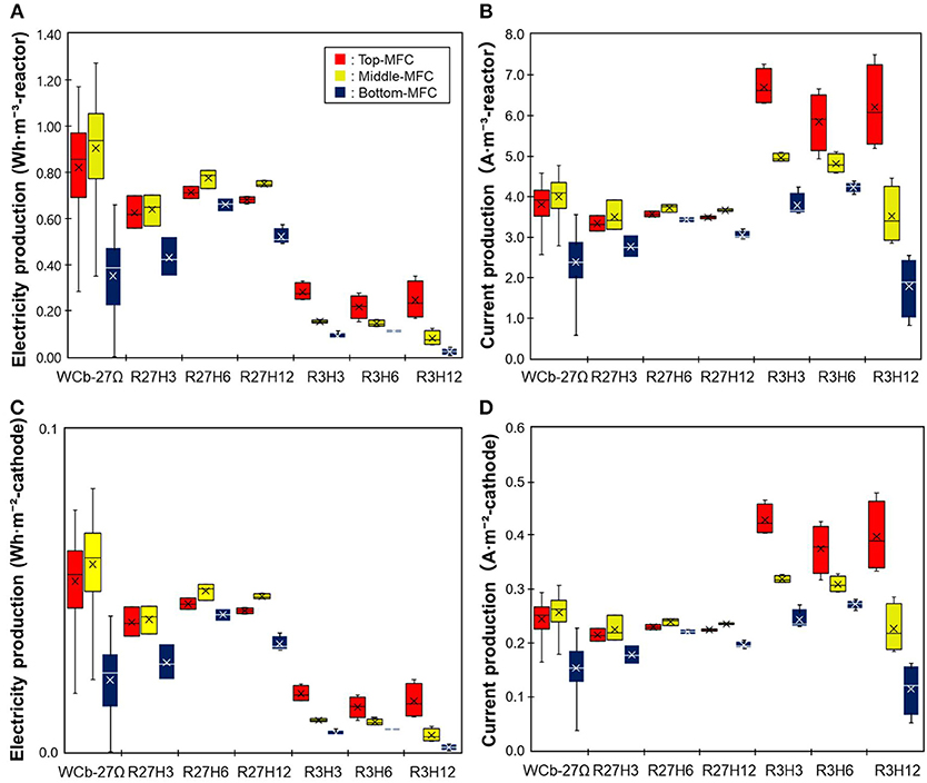
Figure 3. A comparison of the electricity production by the MFCs operated under six different conditions. (A,B) indicate electricity and current production, respectively, normalized by the reactor volume. (C,D) indicate electricity and current production, respectively, normalized by the cathode area.
COD Removal via MFCs in the Chemostat Reactor
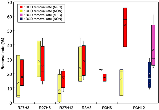
Figure 4 shows the results of COD removal by the IN-MFC in the chemostat reactor. Compared with the NON reactor, the COD significantly decreased only under R3H12 while no significant differences between the NON and MFC reactors were observed under the other conditions. Specifically, the average COD removal efficiency (COD-RE) was 54 ± 14% in the reactor with the MFC and 17 ± 10% without the MFC. Under the other conditions, the COD-RTs were in the range of 8.0–45%. For R3H12, the BOD also showed a significant decrease with the MFC reactor. The BOD removal efficiency in the MFC reactor was, on average, 37 ± 17%, which was higher than the BOD removal efficiency in the NON (19 ± 9.5%). The COD and BOD of the effluent from the MFC reactor under R3H12 were 210 ± 82 and 320 ± 98 mg·L−1, respectively.
MFC Energy Recovery Efficiency
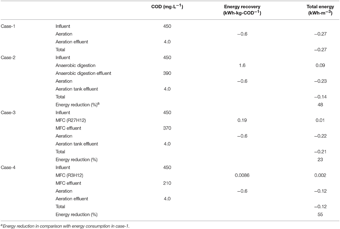
Energy recovery was evaluated based on the electricity production and removal of COD in the chemostat reactor under the six operational conditions, which are indicated as the electricity generation efficiency (EGE, kWh·kg-COD−1) and Coulomb efficiency (CE, %) (Figure 5). The values of both the EGE and CE increased with longer HRTs. The highest EGEMFC, i.e., 0.19 ± 0.12 kWh·kg-COD−1, was observed during R27H12, with a value that was 2.5- and 5.4-fold higher than the EGEMFCs for the 6 and 3 h HRTs, respectively. The CE was also highest during R27H12h (30 ± 18%) but the value was not significantly different under R3H12 (15 ± 7.5%) and R3H6 (19 ± 0.7%). Representative data obtained in the MFC are summarized in Table 1.
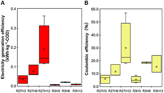
Figure 5. The electricity generation efficiency (A) and Coulombic efficiency (B) for the MFCs operated under 6 different conditions.
Energy Balance Calculations of the MFC-Integrated Wastewater Treatment
Based on the COD-RE and EGE, we calculated the energy consumption for three wastewater treatment scenarios, i.e., aeration (Case-1), a combination of anaerobic degradation and aeration (Case-2), and a combination of aeration and MFC under R27H12 (Case-3) and R3H12 (Case-4) (Tables 1, 2). In Case-2, biomass energy was tentatively retrieved by CH4 fermentation based on the calculations. The EGE via CH4 fermentation (EGECH4) have never evaluated for sewage water. however, data for swine wastewaters, are in the range of 0.79–2.6 kWh·kg-COD−1, with an average of 1.6 kWh·kg-COD−1 (Lo et al., 1994; Hill and Bolte, 2000; Song et al., 2010; Duda et al., 2015; Supplementary Table 2). The EGE in the MFC (EGEMFC) was 0.19 ± 0.12 kWh·kg-COD−1 during R27H12 in Case-3 and 0.0086 ± 0.0025 kWh·kg−1-COD during R3H12 in Case-4. The EGEMFC was <15 and 1% of the EGECH4 under R27H12 and R3H12, respectively. However, taken together with the energy consumption associated with the removal of COD via aeration, i.e., −0.6 kWh·kg-COD−1 (He, 2013; Maktabifard et al., 2018), the system integrated with an MFC operated under R3H12 is advantageous in comparison with systems integrated with CH4-fermentation and an MFC polarized at 27Ω (Table 2). Although the MFC that operated under R27H12 consumed more energy than the CH4-fermentation-integrated system, the MFC that operated under R3H12 can reduce the energy consumption by 55%, which was higher than that for the CH4-fermentation-integrated system (48%). This calculation indicates that the removal of COD without aeration had more of an effect on the total energy balance as compared with the electricity production.
Discussion
This is the first study to investigate the long-term operation of an MFC using an AEM in sewage water. The observed performance was compared with other MFCs that have a capacity >2.0 L and operate in real wastewater (Table 1). The best EGEMFC and CE in the MFC were 0.19 ± 0.12 kWh·kg-COD−1 and 30%, respectively, which are comparable to previously reported MFCs (Feng et al., 2014; Dong et al., 2015; Hiegemann et al., 2016). Several strategies can be considered to increase the energy balance, i.e., an increase in the MFC filling rate (Park et al., 2018) and HRT (Hiegemann et al., 2016) or a decrease in the energy consumed by aeration via a combination with the anaerobic membrane reactor (Ren et al., 2014). However, these strategies do not have practical applications in sewage water treatment due to the two major functions of sewage water treatment plants, i.e., controlling the water quality, including the concentration of dissolved oxygen, and the drainage of storm water. Increases in the COD-RE, electricity recovery normalized by the electrode-area and cathode specific surface area are important factors as reported previously (Logan et al., 2015).
The MFC configuration used in this study was specially designed for its application to sewage treatment plants characterized by both a high influent volume and fluctuations in water levels due to rain water. Moreover, these treatment plants have been widely constructed in Japan. The tubular structure is physically tough, the floating structure can be adapted to changes in the water level, and the core-air chamber allows a simple installation into the existing sewage treatment plant without the construction of a reactor. However, a simple but serious problem was encountered during the installation of the MFC in the sewage water channel. This was the leakage of sewage water into the air-chamber of the MFC at a depth of 1.0 m. The main reactor tank in the sewage water treatment plant generally has a depth of 3.0–5.0 m. However, the operation of single chamber-MFC at more than 1.0 m of water depth has never been reported, to the best of our knowledge, while many large-scale MFCs have been constructed (Ge and He, 2016; Hiegemann et al., 2016; Lu et al., 2017; Liang et al., 2018). Additionally, the MFC with water leakage showed a gradual decrease in electricity production, which was possibly caused by corrosion. On the other hand, the MFC units that did not experience water leakage, i.e., the top and middle MFCs in the IN-MFC module had nearly constant current production in 230 days of operation (Supplementary Figure 3), suggesting no deterioration of electrode and membrane in this duration. In our MFC configuration, AEM elasticity caused water leakage. These membranes shrink upon drying and expand in water. For the longer running MFCs using elastic separator at various depths, further improvement is required in the MFC configuration.
In conclusion, an AEM can be used in a single chamber MFC with a comparative level of electricity production that has been observed for other single chamber MFCs that use a CEM. Within 230 days of the experimental duration, deterioration was not observed in the MFCs did not experience water leakage. The application of the MFCs to wastewater treatment at depths >1.0 m requires technical advancements and further research. Preliminary calculation of energy balance of the system combined MFC and aeration, the MFC having more COD-removal rather than electricity production is advantageous in the total energy reduction.
Data Availability
The raw data supporting the conclusions of this manuscript will be made available by the authors, without undue reservation, to any qualified researcher.
Author Contributions
MS performed MFC experiments and analyzed the data and described the draft of the manuscript. NY designed the experiments and revised the manuscript. KI designed the experiment.
Funding
This study received funding from the MEXT/JSPS KAKENHI (Grant number: 18K18876) and Hibi Science Foundation.
Conflict of Interest Statement
This study was partially funded by Nippon Koei Co., Ltd. and Tamano Consultants Co., Ltd. KI was an employee of Nippon Koei Co., Ltd. We are currently applying for a patent for the MFC configuration reported in this study. All authors acknowledge the scientific fairness of the experimental design and interpretation of the results.
Acknowledgments
We are grateful to Mitsuhiro Sakoda (Tamano Consultants Co., Ltd.), Hirokazu Matsubara (Nippon Koei Co., Ltd.), and Yoshinori Genda (Tamano Consultants Co., Ltd.) for their management of the on-site evaluation. We would like to show our appreciation to Dr. Yasushi Miyata (Nagoya Municipal Industrial Research Institute) for his advice regarding the use of the AEM as a separator in the MFC. We also thank Akihiro Iwata and Yoshimasa Suzuki for their extensive efforts in optimizing the procedure to manufacture the MFC and technical advice on fixing the AEM to the solid frame of the MFC. We also extend our gratitude to the staff of Nagoya City Waterworks & Sewerage Bureau for providing us a venue for the on-site evaluation.
Supplementary Material
The Supplementary Material for this article can be found online at: https://www.frontiersin.org/articles/10.3389/fenrg.2019.00091/full#supplementary-material
References
Arcila, J. S., and Buitrón, G. (2016). Microalgae–bacteria aggregates: effect of the hydraulic retention time on the municipal wastewater treatment, biomass settle ability and methane potential. J. Chem. Technol. Biotechnol. 91, 2862–2870. doi: 10.1002/jctb.4901
Cheng, S., Liu, H., and Logan, B. E. (2006). Power densities using different cathode catalysts (Pt and CoTMPP) and polymer binders (Nafion and PTFE) in single chamber microbial fuel cells. Environ. Sci. Technol. 40, 364–369. doi: 10.1021/es0512071
Dong, Y., Qu, Y., He, W., Du, Y., Liu, J., Han, X., et al. (2015). A 90-liter stackable baffled microbial fuel cell for brewery wastewater treatment based on energy self-sufficient mode. Bioresour. Technol. 195, 66–72. doi: 10.1016/j.biortech.2015.06.026
Du, Z., Li, H., and Gu, T. (2007). A state of the art review on microbial fuel cells: a promising technology for wastewater treatment and bioenergy. Biotechnol. Adv. 25, 464–482. doi: 10.1016/j.biotechadv.2007.05.004
Duda, R. M., da Silva Vantini, J., Martins, L. S., de Mello Varani, A., Lemos, M. V. F., Ferro, M. I. T., et al. (2015). A balanced microbiota efficiently produces methane in a novel high-rate horizontal anaerobic reactor for the treatment of swine wastewater. Bioresour. Technol. 197, 152–160. doi: 10.1016/j.biortech.2015.08.004
Feng, Y., He, W., Liu, J., Wang, X., Qu, Y., and Ren, N. (2014). A horizontal plug flow and stackable pilot microbial fuel cell for municipal wastewater treatment. Bioresour. Technol. 156, 132–138. doi: 10.1016/j.biortech.2013.12.104
Fornero, J. J., Rosenbaum, M., Cotta, M. A., and Angenent, L. T. (2008). Microbial fuel cell performance with a pressurized cathode chamber. Environ. Sci. Technol. 42, 8578–8584. doi: 10.1021/es8015292
Ge, Z., and He, Z. (2016). Long-term performance of a 200 liter modularized microbial fuel cell system treating municipal wastewater: treatment, energy, and cost. Environ. Sci. Water Res. Technol. 2, 274–281. doi: 10.1039/c6ew00020g
Goto, Y., and Yoshida, N. (2017). Microbially reduced graphene oxide shows efficient electricity ecovery from artificial dialysis wastewater. J. Gen. Appl. Microbiol. 63, 165–171. doi: 10.2323/jgam.2016.10.001
He, Z. (2013). Microbial fuel cells: now let us talk about energy. Environ. Sci. Technol. 47, 332–333. doi: 10.1021/es304937e
Hiegemann, H., Herzer, D., Nettmann, E., Lübken, M., Schulte, P., Schmelz, K. G., et al. (2016). An integrated 45 L pilot microbial fuel cell system at a full-scale wastewater treatment plant. Bioresour. Technol. 218, 115–122. doi: 10.1016/j.biortech.2016.06.052
Hill, D. T., and Bolte, J. P. (2000). Methane production from low solid concentration liquid swine waste using conventional anaerobic fermentation. Bioresour. Technol. 74, 241–247. doi: 10.1016/S0960-8524(00)00008-0
Kaur, M., Kumar, M., Sachdeva, S., and Puri, S. K. (2018). Aquatic weeds as the next generation feedstock for sustainable bioenergy production. Bioresour. Technol. 251, 390–402. doi: 10.1016/j.biortech.2017.11.082
Kim, J. R., Cheng, S., Oh, S. E., and Logan, B. E. (2007). Power generation using different cation, anion, and ultrafiltration membranes in microbial fuel cells. Environ. Sci. Technol. 41, 1004–1009. doi: 10.1021/es062202m
Leong, J. X., Daud, W. R. W., Ghasemi, M., Liew, K. B., and Ismail, M. (2013). Ion exchange membranes as separators in microbial fuel cells for bioenergy conversion: a comprehensive review. Renew. Sustain. Energy Rev. 28, 575–587. doi: 10.1016/j.rser.2013.08.052
Li, S., Cheng, C., and Thomas, A. (2017). Carbon-based microbial-fuel-cell electrodes: from conductive supports to active catalysts. Adv. Mater. 29:1602547. doi: 10.1002/adma.201602547
Li, W. W., Yu, H. Q., and He, Z. (2014). Towards sustainable wastewater treatment by using microbial fuel cells-centered technologies. Energy Environ. Sci. 7, 911–924. doi: 10.1039/c3ee43106a
Liang, P., Duan, R., Jiang, Y., Zhang, X., Qiu, Y., and Huang, X. (2018). One-year operation of 1000-L modularized microbial fuel cell for municipal wastewater treatment. Water Res. 141, 1–8. doi: 10.1016/j.watres.2018.04.066
Liu, H., Ramnarayanan, R., and Logan, B. E. (2004). Production of electricity during wastewater treatment using a single chamber microbial fuel cell. Environ. Sci. Technol. 38, 2281–2285. doi: 10.1021/es034923g
Lo, K., Liao, E., and Gao, Y. (1994). Anaerobic treatment of swine wastewater using hybrid UASB reactors. Bioresour. Technol. 47, 153–157. doi: 10.1016/0960-8524(94)90114-7
Logan, B., Cheng, S., Watson, V., and Estadt, G. (2007). Graphite fiber brush anodes for increased power production in air-cathode microbial fuel cells. Environ. Sci. Technol. 41, 3341–3346. doi: 10.1021/es062644y
Logan, B. E., Hamelers, B., Rozendal, R., Schröder, U., Keller, J., Freguia, S., et al. (2006). Microbial fuel cells: methodology and technology. Environ. Sci. Technol. doi: 10.1021/es0605016
Logan, B. E., Wallack, M. J., Kim, K. Y., He, W., Feng, Y., and Saikaly, P. E. (2015). Assessment of microbial fuel cell configurations and power densities. Environ. Sci. Technol. Lett. 2, 206–214. doi: 10.1021/acs.estlett.5b00180
Lu, M., Chen, S., Babanova, S., Phadke, S., Salvacion, M., Mirhosseini, A., et al. (2017). Long-term performance of a 20-L continuous flow microbial fuel cell for treatment of brewery wastewater. J. Power Sources 356, 274–287. doi: 10.1016/j.jpowsour.2017.03.132
Maktabifard, M., Zaborowska, E., and Makinia, J. (2018). Achieving energy neutrality in wastewater treatment plants through energy savings and enhancing renewable energy production. Rev. Environ. Sci. Biotechnol. 17, 655–689. doi: 10.1007/s11157-018-9478-x
Martinez-Sosa, D., Helmreich, B., Netter, T., Paris, S., Bischof, F., and Horn, H. (2011). Anaerobic submerged membrane bioreactor (AnSMBR) for municipal wastewater treatment under mesophilic and psychrophilic temperature conditions. Bioresour. Technol. 102, 10377–10385. doi: 10.1016/j.biortech.2011.09.012
Nurmiyanto, A., Kodera, H., Kindaichi, T., Ozaki, N., Aoi, Y., and Ohashi, A. (2017). Dominant Candidatus Accumulibacter phosphatis enriched in response to phosphate concentrations in EBPR process. Microbes Environ. 32, 260–267. doi: 10.1264/jsme2.me17020
Park, Y., Nguyen, V. K., Park, S., Yu, J., and Lee, T. (2018). Effects of anode spacing and flow rate on energy recovery of flat-panel air-cathode microbial fuel cells using domestic wastewater. Bioresour. Technol. 258, 57–63. doi: 10.1016/j.biortech.2018.02.097
Ren, L., Ahn, Y., and Logan, B. E. (2014). A two-stage microbial fuel cell and anaerobic fluidized bed membrane bioreactor (MFC-AFMBR) system for effective domestic wastewater treatment. Environ. Sci. Technol. 48, 4199–4206. doi: 10.1021/es500737m
Rozendal, R. A., Hamelers, H. V. M., and Buisman, C. J. N. (2006). Effects of membrane cation transport on pH and microbial fuel cell performance. Environ. Sci. Technol. 40, 5206–5211. doi: 10.1021/es060387r
Shizas, I., and Bagley, D. M. (2004). Experimental determination of energy content of unknown organics in municipal wastewater streams. J. Energy Eng. 130, 45–53. doi: 10.1061/(ASCE)0733-9402(2004)130:2(45)
Song, M., Shin, S. G., and Hwang, S. (2010). Methanogenic population dynamics assessed by real-time quantitative PCR in sludge granule in upflow anaerobic sludge blanket treating swine wastewater. Bioresour. Technol. 101(Suppl. 1), S23–S28. doi: 10.1016/j.biortech.2009.03.054
Yan, P., Qin, R. C., Guo, J. S., Yu, Q., Li, Z., Chen, Y. P., et al. (2017). Net-zero-energy model for sustainable wastewater treatment. Environ. Sci. Technol. 51, 1017–1023. doi: 10.1021/acs.est.6b04735
Yoshida, N., Goto, Y., Miyata, Y., and Thakur, V. K. (2016c). Selective growth of and electricity production by marine exoelectrogenic bacteria in self-agregated hydrogel of microbially reduced graphene oxide. J. Carbon. Res. 2:15. doi: 10.3390/c2020015
Yoshida, N., Miyata, Y., Doi, K., Goto, Y., Nagao, Y., Tero, R., et al. (2016a). Graphene oxide-dependent growth and self-Aggregation into a hydrogel complex of exoelectrogenic bacteria. Sci. Rep. 6:21867. doi: 10.1038/srep21867
Yoshida, N., Miyata, Y., Mugita, A., and Iida, K. (2016b). Electricity recovery from municipal sewage wastewater using a hydrogel complex composed of microbially reduced graphene oxide and sludge. Materials (Basel). 9:742. doi: 10.3390/ma9090742
Zhang, X., Cheng, S., Huang, X., and Logan, B. E. (2010). Improved performance of single-chamber microbial fuel cells through control of membrane deformation. Biosens. Bioelectron. 25, 1825–1828. doi: 10.1016/j.bios.2009.11.018
Zhang, X., Pant, D., Zhang, F., Liu, J., He, W., and Logan, B. E. (2014a). Long-term performance of chemically and physically modified activated carbons in Air cathodes of microbial fuel cells. ChemElectroChem 1, 1859–1866. doi: 10.1002/celc.201402123
Keywords: microbial fuel cell, sewage water treatment, anion exchange membrane, organic matter reduction, energy balance
Citation: Sugioka M, Yoshida N and Iida K (2019) On Site Evaluation of a Tubular Microbial Fuel Cell Using an Anion Exchange Membrane for Sewage Water Treatment. Front. Energy Res. 7:91. doi: 10.3389/fenrg.2019.00091
Received: 25 June 2019; Accepted: 16 August 2019;
Published: 06 September 2019.
Edited by:
Eileen Hao Yu, Newcastle University, United KingdomReviewed by:
Xu Wang, Wuhan University, ChinaQaisar Mahmood, COMSATS University, Islamabad Campus, Pakistan
Copyright © 2019 Sugioka, Yoshida and Iida. This is an open-access article distributed under the terms of the Creative Commons Attribution License (CC BY). The use, distribution or reproduction in other forums is permitted, provided the original author(s) and the copyright owner(s) are credited and that the original publication in this journal is cited, in accordance with accepted academic practice. No use, distribution or reproduction is permitted which does not comply with these terms.
*Correspondence: Naoko Yoshida, eW9zaGlkYS5uYW9rb0BuaXRlY2guYWMuanA=
†These authors have contributed equally to this work
 Mari Sugioka
 Naoko Yoshida
 Kazuki Iida2