 Song Li
 Zhijian Zhang
 Qian Zhang
 Chen Hao
- Fundamental Science on Nuclear Safety and Simulation Technology Laboratory, Harbin Engineering University, Harbin, China
To meet the requirements of one step lattice calculation on resonance effect, a self-developed design and construction of a resonance treatment code are composed based on subgroup method and HELIOS-1.11 library. Subgroup fixed source equations are solved by method of characteristics to get subgroup fluxes, which are subsequently used to deduce effective resonance cross sections combined with subgroup weights and subgroup levels. Bondarenko method is employed to handle resonance interference effect and a resonance category scheme and resonance geometry simplification method are introduced to improve efficiency. Benchmarks of single pin cells and assemblies of light water reactor are adopted for numerical validation and the calculating results indicate that this method can treat resonance effect both precisely and effectively.
Introduction
In traditional lattice physics codes, the three-step method and pin-by-pin method are widely used in light water reactor calculation (Cacuci, 2010). Three-step method firstly adopts detailed numerical analysis on fuel cell or lattice scale, the regional homogenization is carried out subsequently and the last step is the diffusion or transport calculation for the whole core. By contrast, pin-by-pin method has two steps (Choi et al., 2017), namely assembly transport calculation and a reactor core calculation. However, three-step method and pin-by-pin method both consider the fuel cell or assembly as a unity, so nuclide reaction inside the fuel area cannot be taken into consideration in detail. To handle this problem, one-step method without any approximation for fuel cell and assembly has become the researching focus currently (Downar et al., 2016). One of the most significant parts of one-step method is treating resonance self-shielding problem effectively and precisely since it provides material cross section for the whole calculating process. Traditional methods for resonance treatment are equivalent method (Askew et al., 1965; Zhang et al., 2015), which is based on the equivalence between heterogeneous and homogenous problems and the ultra-fine group method with extremely detailed division of groups (Ishiguro and Takano, 1971). The former method has good efficiency but shows obvious drawbacks in accuracy and geometry adaptability, while although the latter one has a satisfactory accuracy, it's hard to be applied to lattice scale problems since the calculating burden is unacceptable. Other methods such as embedded self-shielding method and pseudo-isotope-method have been further developed in recent years, but problems for detailed region in fuel cell is still up in the air (Liu et al., 2018; Zhang et al., 2018).
In recent years, subgroup method is proved to have advantages in solving complex geometry problems with high accuracy and also has a good performance for sub-pin scale (Nikolaev et al., 1971; Li et al., 2018), so it has been one of the research hotspots of resonance treatment. Different from traditional method, subgroup method divides the subgroups by cross section value and the effective resonance cross section is calculated by subgroup parameters. By combining with transport module capable of handling problems with arbitrary geometry, subgroup method can be applied to any kind of lattice geometry. In this work, subgroup method combing with method of characteristics is adopted to treat resonance self-shielding effect.
Subgroup fixed source problems (SGFSP) are established to obtain subgroup fluxes (Jung et al., 2013), which are used subsequently to deduce effective resonance cross sections. For problems with various number of resonant isotopes, resonance interference effect is taken account by Bondaronko iteration method (Casal, 1991). In this procedure, while treating current resonant isotope, cross sections of other resonant isotopes are firstly considered as hypothetical values and then be updated by the values of the previous iteration step. It can be seen that SGFSP and resonance interference effect treatment occupy the most calculating time so optimizing method has been taken in this work to improve efficiency. In this case, we use a smaller number of subgroups in SGFSP for simplification while a larger number of subgroups in deducing effective cross section to ensure accuracy, and an extrapolation of relevant data obtained by SGFSP is used between these two set of subgroups. In addition, a resonance category is introduced to divide resonant isotopes into different categories and each category has been assigned with a representative isotope. SGFSPs are carried out according to representative isotopes and only interference of isotopes in the same category are taken into consideration. What's more, geometry setting of transport and resonance calculation are not necessarily to be the same and resonance treatment could adopt a simpler division with fewer sub-regions to predigest calculation burden.
In this work, a resonance calculating code is developed based on the method above and HELIOS-1.11 library. To verify the calculating results of this work, a series of benchmark including single cell and two-dimensional lattice released by Japan Atomic Energy Research Institute (JAERI) is employed for numerical verification and analysis (Yamamoto et al., 2002), and the calculating results indicate a good performance of method introduced in this work. Since this work provides effective material cross sections for the whole reactor physics calculation precisely and efficiently, it will serve as an important component for project of research on key technology of numerical reactor engineering in Harbin Engineering University. This work will also be coupled with transient, burn-up, and thermal hydraulic feedback module developed in this project for the further researches, which will not be illustrated here since we only concentrate on resonance calculation in this paper. This work is a redevelopment of HELIOS-1.11 program as they share the same neutronic functions. However, Different from HELIOS-1.11 code, which is written by outdated FORTRAN77 language, program of this work adapts C language for redesigning since it is more compatible to different operation systems and has the direct access to physical addresses as well as hardware operating. Besides, the resonance treatment procedure is coupled with an in-house developed MOC transport code rather than CCCP module used in HELIOS1-11. The independent design and construction of a completed lattice physics analyze code is realized.
Therotical Model
Subgroup Method
Subgroup parameters consist of subgroup level and subgroup weight. As shown in Figure 1. The resonance group is divided into 4 subgroups and the subgroup levels indicate the 4 discrete cross sections from σ1 to σ4, while subgroup weights w1 to w4 stand for the probability of the neutrons from this resonance group locating in each subgroup respectively. Take the absorption cross section for an example, if there are I subgroups in resonance groupg, effective cross section can be shown as follows:
In Equation (1), φi is the subgroup flux. To obtain this value, subgroup fixed source equations which have the same format as Boltzmann transport equation are solved. SGFSP can be solved by any type of transport method, such as method of characteristics. The deduction process of this procedure is introduced as follows.
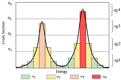
Figure 1. Subgroup parameters in a resonance group.
In light water reactors, energy of neutrons produced by fission reaction is relatively high, and nearly up to 99.5% of these neutrons are among the fast group range (Hebert, 2009). Therefore, it can be assumed that the fission source of resonance groups is negligible. In addition, up-scattering effect is also insignificant in resonance range, so the source term in this energy range only consists of down-scattering reaction from groups with higher energy. In this condition, for subgroup i in resonance group g, a fixed source equation can be written as follows:
In Equation (2), λg is the intermediate resonance factor and Σb, g is macroscopic background cross section and its definition is shown in Equation (3), in which M is the total number of nuclides types, Nmand Σp, g, mare the number density and potential scattering cross section of resonant nuclide m respectively.
In Equation (2), scattering cross section are made up by potential scattering cross section and resonance scattering cross section, while the latter is only non-zero for resonant isotopes. However, for simplification, resonance scattering cross section is also considered to be zero for resonant isotope in this work as resonance scattering integrals are not stored in the HELIOS library (Stammal'er, 2008). To compensate for this approximation, resonance absorption integrals in HELIOS library is adjusted during the producing process. Therefore, resonance scattering will not be taken into consideration and the final fixed source equation can be expressed as Equation (4). It can be seen that the source item of Equation (4) has no connection with flux, so it means that SGFSP can avoid the source iteration process of transport calculation, which will be much easier and more efficient for MOC module to solve. When subgroup fluxes are solved by transport module, effective resonance cross sections can be obtained by Equation (1).
Optimizations for SGFSP
Although solving SGFSP is much less time-consuming compared with Boltzmann transport equation, it still accounts for the vast majority of calculating time of subgroup method. Theoretically, subgroup method needs to carry out SGFSPs for each nuclide and each resonance group respectively, which is very time-consuming and accounts for the majority of the whole resonance calculating process. Therefore, the main purpose of the optimizations for SGFSP is to reduce the total number of subgroup fixed source equations, and the key part of this procedure is to reduce the total number of subgroups in all resonance groups.
Learned from the definition of subgroup method, each resonance group has a set of subgroup parameters and SGFSPs are carried out group by group. However, from Equation (4), we find that only subgroup levels are used in SGFSP, while subgroups weights are only used in the subsequent process of effective cross section calculation. For subgroups with the same level, no matter what values their subgroup weights are, they will have the same solution for SGFSP according to Equation (4). In this condition, the more subgroups have the same level, the less calculating burden it will be. If all resonance groups have the same set of subgroup levels, SGFSP would only need to be carried out in one resonance group.
In the procedure of generating traditional subgroup parameters (Cullen, 1977), the fuel is supposed to be composed of one resonant nuclide R and one moderator nuclideH. Therefore, the flux of the uniform condition can be written as follows
In Equation (2), Σa and σa are absorption cross sections, Σp and σp are potential scattering cross sections. In this condition, the unknown values in Equation (5) are only subgroup levels and subgroup weights. As is discussed above, it should be arranged that every resonance group has the same set of subgroup levels but different subgroup weights. In this case, the subgroup level should be pre-specified by trial and error (Joo et al., 2009), and subgroup weights will be the only un-known value left. The multi-group libraries always store resonance integral data, which can be interpolated with background section and temperature. Take the absorption cross section for example, by selecting K resonance integrals of different background cross sections in the library, the subgroups weights with subgroup number of I can be obtained through optimum fitting method, which is shown in Equation (6)
On the other hand, observed from Figure 1, the more subgroups number is adopted, the more precise to describe the resonance effect. However, it's not necessary to calculate SGFSP with that many subgroups since subgroup fluxes are able to be interpolated (Park and Joo, 2018). Therefore, a set of subgroup parameters with fewer group number could be used in SGFSP to improve efficiency while another set of subgroup parameters with an extensional number of groups are used to calculate effective cross section to guarantee the accuracy. In this work, the number of subgroups in SGFSP is 4 and the latter one is set to be 7. To determine the subgroup levels, an iteration process is adopted. First, an initial set of subgroup levels is selected randomly, such as by geometric progression. Then the subgroup weighs can be generated by Equation (6). Through this set of subgroup parameters, resonance integral can be reproduced and its root-mean-square error (rmse) compared with the reference value is obtained. Subsequently, the values of subgroup levels are modified by a slight increase. If the new rmse also increase then the subgroup level should be adjusted to be diminished, vice versa, until the variations of rmse meet the converge criteria, which is set to be 0.05 and the maximum iteration number is 50. Take the absorption cross section of U-238 for an example, the variation of its resonance integral (RI) by background cross section (BCS) in energy range between 5.72 and 7.34 eV and temperature of 300 K is shown in Table 1A. By comparison, subgroup parameters of both 4 and 7 subgroups are given in Table 2.
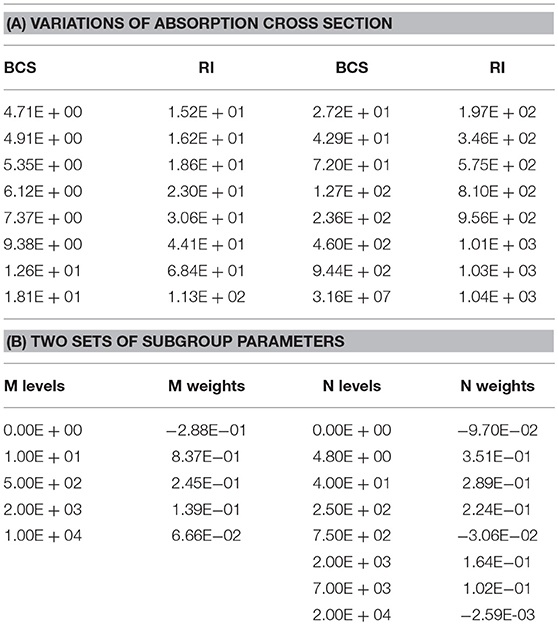
Table 1. Absorption resonance integral of U-238 in 5.72–7.34 eV and its subgroup parameters.
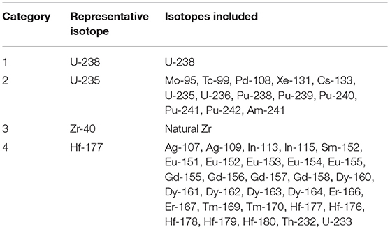
Table 2. Resonance categories and representative isotopes.
Observed from Table 1A, absorption resonance integral of U-238 in this energy range shows a rapid rise by background cross section, which indicates a significant resonance peak occurs in this range. In Table 1B, M indicates for subgroup number of 4 and N indicates for subgroup number of 7. It is worthwhile to mention that if the sum of M or N subgroup weights are not equal to 1, another subgroup whose level is 0 is added and its weight is calculated by 1−∑wi. What's more, it can be noticed that some subgroup parameters are not physical, such as 0 level, negative weights and the largest M and N level are both more than the actual largest cross section value in Table 1A. This phenomenon results from the procedure of Equation (6). Since it is not subgroup parameters values but the final effective cross section in Equation (1) that matters, the non-physical subgroup values are acceptable as long as the accuracy of Equation (1) is ensured. After SGFSP is carried out by M levels, an extrapolation method is adopted to get relevant values for N subgroups. The detailed procedure is shown as follows.
Combing Equations (1) and (5), the relationship between effective absorption cross section and background cross section can be deduced as Equation (7). After SGFSP is solved and subgroup flux is obtained, σb, i can be calculated respectively for 4 subgroups according to Equation (8). However, it is not σb, i that is used in interpolation. In practical heterogeneous system, there is an equivalence theorem which indicating σb, i should be augmented by an equivalence cross sectionσe, i. In this way, σb, i = λσp+σe, i (Stammal'er, 2008). When σb, i is acquired, σe, i can be calculated just by subtracting λσp from σb, i. Therefore, a set of σe, i with dependence of σa, ifor 4 subgroups is established and the interpolation process is carried out between σe, i and ln (σa, i).
Resonance Interference Effect and Resonance Category
Method above is deduced on the basis that there is only one resonant isotope existing in the fuel area, which is not corresponding with actual condition. Traditional fuel used in light water reactors is composed of different kinds of uranium isotopes and in the process of burn-up, varieties of heavy isotopes will be generated and a considerable portion of them are resonant. Different resonance peaks of different isotopes will overlap with each other and this phenomenon is known as resonance interference effect.
Under these circumstances, while calculating the current resonant isotopes, the impact of resonance peaks of other resonant isotopes must be taken into consideration and Equation (7) is modified to capture this influence. Take the absorption cross section for an example, we define a pseudo cross section σx to represent the absorption contributions of the other resonant isotopes and the effective cross section can be shown as Equation (9).
In Equation (9), m represents the resonant isotope in concern while n means other resonant isotopes. However, since calculating σx requires the absorption cross section of other resonant isotopes, whose value is unknown in the beginning, the Bondarenko iteration process (Cacuci, 2010) will be introduced in this process. At the very start, σx is assumed to be zero in Equation (9), then the newly acquired σa will be used in the second round of calculation and this process will be repeated to convergence. The convergence criterion is set that σa should not be different more than 10−3 compared with the previous iteration. The maximum number of iteration is set to be 30 and a relaxation factor of 0.5 is applied to accelerate the convergence process.
However, according to Bondarenko method above, each type of resonance isotopes should be taken into account and the number of iterations will sharply increase with the number of resonant isotopes. During the burn-up process, the calculating efficiency will become unacceptable. Therefore, there is a critical need for simplification of the resonance interference effect. In this work, according to the shape of resonance peak, different resonant isotopes can be divided into several categories (Stammal'er, 2008). Isotopes in the same category have similar property and the isotope with the most prominent absorption character is chosen as the representative isotope in each category. As U-238 is the most domain resonance isotope, it is classified as a single category containing only itself. Other Heavy mass isotopes and fission neutron productions are specified as a category due to its absorption or fission characters, and U-235 is assigned as its representative isotope. If Nature Zr is treated as resonance isotope, particular subgroup parameters can be used. However, in many cases resonance of Nature Zr does not matter much so only temperature interpolation is needed to get its cross section from pre-stored values. For other resonance isotopes such as control rod materials or strong absorbers like gadolinium isotopes, they are treated as another category and Hf-177 is assigned as representative isotope. The detailed resonance categories and representative isotopes are shown in Table 2. In SGFSP, only resonant isotopes of the same category will be treated and the influence of other categories is assumed to be insignificant. In addition, isotopes of the same category all adopt subgroup parameters of representative isotope in SGFSP.
It can be noticed that cross sections in Equation (4) is group dependent, so there is a group-averaged calculation by weight of infinitely diluted resonance integrals. For regions with resonant isotopes, group-averaged calculation can be shown as the left side of Equation (10) while the right side for regions without resonant isotopes.
In Equation (10), m ∈ k represents the isotopes belonging in the same category, RIm, g, ∞is infinity diluted resonance integral of group for isotopem, Δug is the lethargy width of resonance group g. On the right side, RIr, g, ∞is the infinity diluted resonance integral for representative isotope of the category in calculation. In this condition, extrapolation variable ln (σa, i) is also adjusted by multiplying a modifying factor F toσa, i, which is shown in Equation (11).
Geometry Setting and Program Design
In transport module, a fine mesh will be set to decompose the region and each mesh is considered to be a flat source region, in which the source is assumed to the same (Jung et al., 2013). As is shown in Figure 2A, each cell is divided into 4 rings along the radial direction and each ring is also divided into 8 sectors. According to this geometry, there are 64 flat source regions containing resonant isotopes, where SGFSP and Bendarenko iteration will be carried out respectively. For regions only with non-resonant isotopes, no specific treatment is needed other than interpolation with temperature. However, on the beginning of life for a reactor, regions in the same fuel pin will have exactly the same materials. In this case, it can be assumed that resonance cross section of a certain isotope will only vary dramatically along radius due to space self-shielding, while regions with the same radius will have the same cross section. Therefore, geometry setting for resonance treatment can be simplified as shown in Figure 2B, which only reserve the region decomposition along the radius direction while sectors along the ring are neglected. Through this simplification, only 8 regions have resonant isotopes and numbers of iterations and memory usage will decrease dramatically. Calculating process of this part is shown as follows.
1. Based on the transport module, SGFSPs are solved according to geometry in Figure 2A to obtain fine mesh subgroup fluxes.
2. Ring-wise subgroup fluxes for geometry in Figure 2B are calculated by volume-weighted method, and subsequent resonance treatment will all adopt ring-wise geometry to obtain material cross section.
3. Fine mesh in Figure 2A will continue to be used in the transport module for eigenvalue calculation. At this time, sectors in the same ring will have the same cross sections.
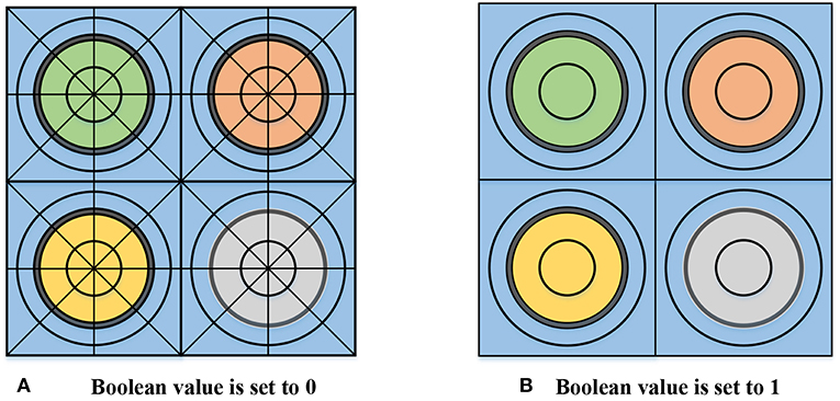
Figure 2. Geometry setting for resonance treatment. (A) Boolean value is set to 0, (B) Boolean value is set to 1.
In this work, both resonant and non-resonant cross section treatment will be carried out after completing geometry treatment of transport module, which will provide all the geometry information needed in resonance treatment. Geometry information is defined in transport input file while the material information is defined in material input file separately. After SGFSP cross sections are set, fixed source solver of transport module will be called to obtain SGFSP fluxes, which will be used afterward in resonance interference and removal correction to obtain effective material cross sections. The final effective material cross section will be stored in variables defined by the transport module when the resonance treatment is completed. Transport module will continue to carry out the eigenvalue calculation. By coupling with MOC and CMFD module, this work is capable to treat 2D or 3D scale problems. Moreover, as cross section treatment can be handled by each region independently, the parallel calculation based on domain decomposition is applied in this work. Flow chart of the whole calculating process is shown in Figure 3.
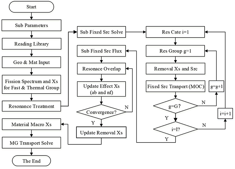
Figure 3. Flow chart of resonance treatment.
Numerical Validation
This work adopts the 47 energy group structure of HELIOS-1.11 (Kim et al., 2015) based on the ENDF VI library, in which the resonance range is from 1.855 to 9118 eV. Benchmark used in this work is selected from light water reactors which contains UO2 and MOX fuels with both fuel pin cell and PWR fuel assembly (Yamamoto, 2004) and subgroup method illustrated in this work will be used to calculate these problems. It is worthwhile to mention that HELIOS-1.11 program is applied as a code-to-code benchmark for the verification of the new developed code of this work. The reference values of pin cell and lattice problems are both provided by the report issued by Japan Atomic Energy Research Institute (Yamamoto et al., 2002).
Single Cell Problems
Single cell problems contain two typical cases. One is a typical UO2 pin and the other is a MOX pin, number densities of isotopes contained in these two problems are shown in Table 3. These two cases have the same geometrical configuration and dimension, which is shown in Figure 4. In addition, the burn-up processes of these two problems are also analyzed.
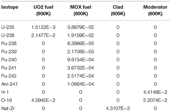
Table 3. Number densities of nuclides of UO2 and MOX pin (barn/cm).
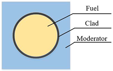
Figure 4. Geometry configuration of single fuel cell.
In the first problem, resonant isotopes include only U-238 and U-235 while the latter one also has plutonium and actinium isotopes. It has a great increment of isotopes accumulated during the burn up process and more than 100 isotopes would be generated, and more than 20 of them are resonant isotopes. Pin-averaged absorption cross sections of U-238 and U-235 of these two cases and Pu-239 and Pu-241 of MOX pin are shown in Figures 5–7, respectively. Figure 8 gives the eigenvalue calculated during the whole burn-up process with 73 steps. The relative error of cross sections and error of eigenvalue are calculated by Equation (12) and Equation (13) respectively, where subscript x stands for values calculated by subgroup method while ref stands for reference value.
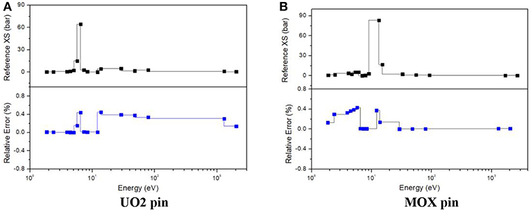
Figure 5. Errors of U-238 absorption cross section of single cell. (A) UO2 pin, (B) MOX pin.
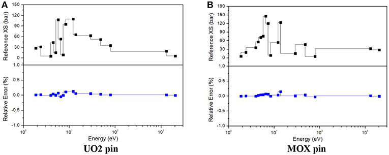
Figure 6. Errors of U-235 absorption cross section of single cell. (A) UO2 pin, (B) MOX pin.
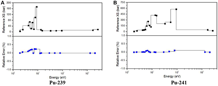
Figure 7. Errors of Pu isotopes absorption cross section of MOX pin. (A) Pu-239, (B) Pu-241.
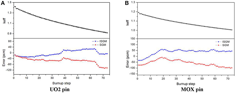
Figure 8. Eigenvalue of single call in each burnup step. (A) UO2 pin, (B) MOX pin.
Learned from Figure 5, improved subgroup method (ISGM) introduced in this work has a good performance to describe the variations of U-238 absorption cross section both in UO2 and MOX pin, of which the largest relative error is <0.6%. It should be noticed that cross sections with energy range from 5~7 to 10~100eV, especially in energy around 6.7 eV, have significant resonance peaks, so that its error shows a moderate rise compared with other energy range. In general, ISGM precisely captured the dramatic change of cross sections as well as resonance interference effect of U-238.
From Figures 6, 7, it can be seen that ISGM has an obvious improvement in figuring up cross sections for U-235 and plutonium isotopes compared with U-238. It is reasonable since resonance peaks them are not as remarkable as those of U-238. The largest relative error of U-235 absorption cross section of UO2 and MOX pin are both <0.3% and errors are no more than 0.1% in most of the energy range. For Pu-239 and Pu-240, errors slightly tend to be upward compared with U-235 since their resonance peaks overlap more intensely with U-238. However, the largest error of plutonium isotopes is still <0.5%, indicating a good performance of ISGM for resonance treatment.
Eigenvalue of the burn-up process is shown in Figure 8. In this process, as the number of resonant isotopes increases dramatically, influence of resonance category is analyzed. In Figure 8, SGM indicates for traditional subgroup method without resonance category and ISGM has adopted resonance category shown in Table 2. It can be seen that error for k effective is <10 pcm for UO2 pin in the beginning for both SGM and ISGM. As the burn-up goes on, errors have an increasing trend with a downwards in the end. The largest error in the whole burn-up process is 29 pcm for ISGM while −98 pcm for SGM, which indicates both methods in this work has a good performance to treat UO2 problems and its burn-up process. As for MOX pin, the error becomes a little bit of larger since resonance isotopes increase. The largest error occurs at the 19th burn-up step with 60 pcm for ISGM while −106 pcm for SGM at the last step, which is also acceptable. ISGM only takes resonant isotopes in the same category into consideration, so that influence of resonance peaks of other resonant isotopes is neglected, making values of cross section smaller than that of SGM and this accounts for the phenomenon that eigenvalue of ISGM is larger compared with SGM. Table 4 compares the calculating burden of SGM and ISGM in the 73rd burn-step of UO2. It can be seen that ISGM can make a considerable reduction of the number of SGFSP equations and also shows an improvement for resonance iteration number. The total time for resonance treatment of ISGM is reduced by 35.5% compared with SGM while the accuracy is also guaranteed.
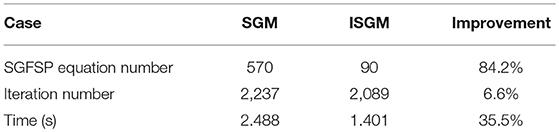
Table 4. Calculation burden of the 73rd path of UO2.
Assembly Problem
Assembly problems consist of a PWR UO2 fuel assembly and a MOX fuel assembly, which are the same geometrical configuration as a traditional 17 × 17 type PWR fuel design. The UO2 assembly is composed of UO2 and UO2-Gd2O3 fuel rods. The geometrical description and the configuration of the assembly geometry are given in Figure 9A. The MOX fuel assembly is the same geometrical configuration as the UO2 fuel assembly. Different from MOX single cell, the assembly is composed of low, middle, and high Pu content fuel rods, which is shown in Figure 9B. Materials of guide tubes and thimble tubes of these two assemblies are the same as clad. Besides, the clad and moderator material are the same as those of single cell problem. In addition, UO2 in the first assembly is the same as that of single cell. Isotope number densities of UO2-Gd2O3 and 3 types of MOX are shown in Table 5. The aim of these lattice problems is to examine the ability of the subgroup method used in this work to capture the resonance effect in strong absorbers and large scale problems. In the calculating procedure, the boundary condition is set to be reflective in all four sides.
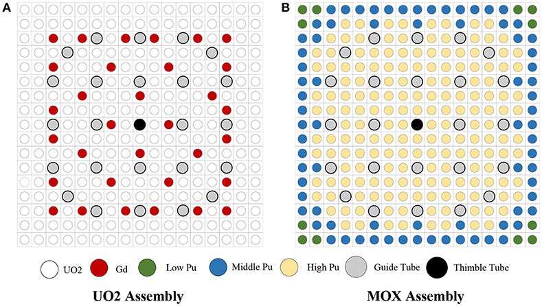
Figure 9. Geometry configuration of 17 × 17 assembly. (A) UO2 assembly, (B) MOX assembly.
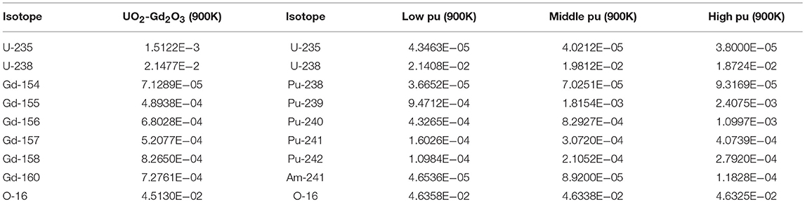
Table 5. Number densities of nuclides of UO2 and MOX assembly (barn/cm).
Due to space self-shielding, fluxes would suffer a sharply decrease from the pin surface to the inner side, making resonance cross sections change dramatically along the radial direction even with the same number density. To describe the detailed cross section distribution, the Gadolinium pin is divided into 8 equal volume rings along the radial direction while the UO2 pins have 3 rings. Each ring is also divided into 8 equal volume sectors in the transport module as fluxes would vary in different region of the same ring because of the asymmetric configuration of the lattice. However, as illustrated before, sectors in the same ring would have the same cross sections despite in reality they are different. To analyze the influence of this simplification, radial distribution of resonance cross sections from 5.72 to 7.34 eV of U-238 in Gadolinium pin and high Pu pin are shown in Figure 10. In this figure, SGM represents for subgroup method with the same geometry as transport module while ISGM represents for resonance effect is calculated in ring-wise scale. In addition, both SGM and ISGM adopts resonance category introduced in Table 2. The reference value is given by fine mesh identical to SGM, which is more precise theoretically.
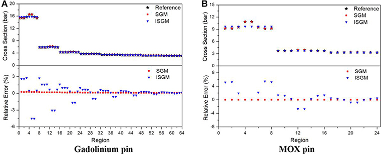
Figure 10. Radial distribution of cross section for 5.72 eV to 7.34 eV of U-238. (A) Gadolinium pin, (B) MOX pin.
For Gadolinium pin, resonance cross sections will change more acutely due to the existence of strong absorbers, especially for regions near the pin surface. It can be seen that even in the same ring, cross sections of the outer-most side vary sharply. SGM can describe this phenomenon accurately and its cross section curve is almost entirely coincided. Errors of SGM are <0.3% in all regions. As for ISGM, it is more like an average value of cross section in the ring, cross sections in the sector-wise region will have a larger relative error compared to the fine-mesh reference value. Calculating results for high-Pu pin have the same tendency, in which errors of SGM are <0.3% while the largest error of ISGM will be more than 5%. The influence of these errors to eigenvalue and power distribution is shown in Table 6 and Figures 11, 12, respectively.

Table 6. Eigenvalue of UO2 and MOX assembly.
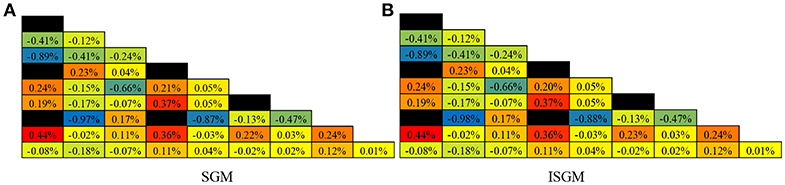
Figure 11. Error distribution of normalized lattice pin power of UO2 assembly. (A) SGM, (B) ISGM.
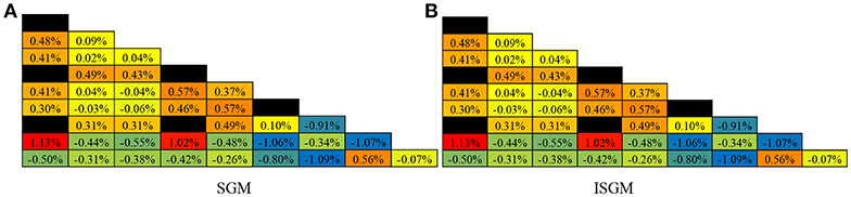
Figure 12. Error distribution of normalized lattice pin power of MOX assembly. (A) SGM, (B) ISGM.
Compared with the reference eigenvalue, errors of SGM and ISGM are both <100 pcm, indicating these two calculating options can both give an accurate effective multiplication factor in spite of different cross sections. Particularly, difference between eigenvalues of SGM and ISGM is negligible as only 1 pcm for both UO2 and MOX assembly. From Figures 11, 12, errors of pin power distribution are also slight as the largest one is <1%. For UO2 assembly, pins around Gadolinium pin have a relatively higher error as strong absorber is harder to deal with in referred to resonance effect. For MOX assembly, relative error for pins in the outer side tend to rise as absolute values of pin power are smaller in this region. In addition, differences of pin power distribution between SGM and ISGM are also insignificant with only 0.1% deviation. In general, accuracy for eigenvalue and pin power distribution of SGM and ISGM are the same satisfying for lattice physics calculation. Table 7 compares the calculating burden of SGM and ISGM in terms of time-consuming and memory cost. It can be seen that ISGM has an obvious improvement in both two aspects as resonance interference effect and geometry setting are simplified. Only 7.8% of total time and 13.5% of total memory is needed for ISGM to provide effective region-wise macro cross sections while accuracy is also assured. In this case, ISGM is a more appropriate method to handle the resonance effect both accurately and effectively.
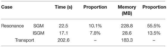
Table 7. Calculation burden of UO2 lattice.
Conclusions
Subgroup method based on HELIOS−1.11 library is adopted to develop the resonance calculating code in this work, which is capable to satisfy the requirement for resonance treatment in one-step reactor lattice physics calculation. This method could be combined with the transport module for arbitrary geometry to get subgroup fluxes for effective cross sections deduction. Through Bondarenko iteration method, resonance interference effect is taken into consideration. In addition, a simplified set of subgroup parameters is used subgroup fixed source problems to improve efficiency while a detailed subgroup flux is interpolated to secure accuracy. Moreover, a resonance category is introduced to simplify the process of resonance interference treatment and a resonance geometry setting is analyzed to reduce the calculating burden of time and memory usage. Series of simplified and original subgroup levels and the integrated resonance category are detailed illustrated in this work. The main innovation point of this work is the realization of independent research and redevelopment of a resonance treatment program, which is capable to incorporate with the in-house transport and burn-up code to compose a complete lattice physics analyzing program. The performance of resonance treatment program is revalidated by a series of publically released benchmarks. Numerical results show that methods used in this work have a good performance in calculating resonance cross sections, the eigenvalue and pin power distribution accurately and effectively.
Author Contributions
SL, QZhang and CH contributed conception and design of the study. SL organized the database, performed the statistical analysis, and wrote the first draft of the manuscript. ZZ and QZhao decide the research contents of this work and give hardware-software support. All authors contributed to manuscript revision, read and approved the submitted version.
Conflict of Interest Statement
The authors declare that the research was conducted in the absence of any commercial or financial relationships that could be construed as a potential conflict of interest.
Acknowledgments
This work is supported by the Research on Key Technology of Numerical Reactor Engineering [J121217001], the Fundamental Research Funds for the Central Universities [GK2150260154], the Heilongjiang Province Science Foundation for Youths [QC201803] and China Scholarship Council.
References
Askew, J., Fayers, F.J., and Kemshell, P.B. (1965). A general description of lattice code WIMS. J. Br. Nuclear Energy Soc. 5, 546–585.
Cacuci, D. (2010). Handbook of Nuclear Engineering. Springer, 1035–1047. doi: 10.1007/978-0-387-98149-9
Casal, J. (1991). “HELIOS: geometric capabilities of a new fuel-assembly program,” in Proceedings International Topical Meeting on Advances in Mathematics, Computations and Reactor Physics, Pittsburgh, PA., USA.
Choi, S., Smith, K. S., Kim, H., and Tak, T. Lee D. (2017). On the diffusion coefficient calculation in two-step light water reactor core analysis. J. Nuclear Sci. Technol. 54, 705–715. doi: 10.1080/00223131.2017.1299648
Cullen, D. (1977). “Calculation of probability table parameters to include intermediate resonance self-shielding,” in Lawrence Livermore National Laboratory, UCRL-79761.
Downar, T., Jabaay, D., Kochunas, B., Collins, B., Stimpson, S., Godfey, A., et al. (2016). “Validation and verification of the MPACT code,” PHYSOR 2016, Sun Valley, ID.
Hebert, A. (2009). Applied Reactor Physics. Montreal, QC: Presses Internationales Polytechnique, 225–228.
Ishiguro, Y., and Takano, H (1971). PEACO: A Code for Calculation of Group Constant of Resonance Energy Region in Heterogeneous Systems. Tokyo: Japan Atomic Energy Research Institute.
Joo, H. G., Kim, G. Y., and Pogosbekyan, L. (2009). Subgroup weight generation based on shielded pin-cell cross section conservation. Annu. Nuclear Energy. 36, 859–868. doi: 10.1016/j.anucene.2009.03.017
Jung, Y. S., Shim, C. B., Lim, C. H., and Joo, H. G. (2013). Practical numerical reactor employing direct whole core neutron transport and subchannel thermal / hydraulic solvers. Annu. Nuclear Energy. 62, 357–374. doi: 10.1016/j.anucene.2013.06.031
Kim, K. S., Wiarda, D. A., and Godfrey, A. T. (2015). “Development of a new 47-group library for the CALS neutronics simulators,” in M&C 2015, Nashville, TN.
Li, S., Zhang, Q., Zhao, Q., and Li, P. (2018). Calculation method for subgroup parameters with accurate resonance interference treatment. Atom. Energy Sci. Technol. 52, 1166–1173
Liu, Z., He, Q., Zu, T., and Cao, L. (2018). The pseudo-resonant-nuclide subgroup method based global–local self-shielding calculation scheme. J. Nuclear Sci. Technol. 55, 217–228. doi: 10.1080/00223131.2017.1394232
Nikolaev, M. N., Ignatov, A. A., Isaev, N. V., and Kokhlov, V. F. (1971). The method of subgroups for considering the resonance structure of cross sections in neutron calculations. Sov. Atom. Energy 30, 528–533. doi: 10.1007/BF01408755
Park, H., and Joo, H. G. (2018). “Effective subgroup method employing macro level grid optimization,” in PHYSOR 2018, Cancun, Mexico.
Yamamoto, A. (2004). Study on the Analyses of the Reactor Physics Benchmark Problem for the LWR Next Generation Fuels. JAERI-Research 2004-004, Research Committee on Reactor Physics, Japan Atomic Energy Research Institute. Available online at: https://rpg.jaea.go.jp/else/rpd/report/report1/LWR-benchmark/index.htm
Yamamoto, A., Tadashi, I., Takuya, I., and Etsuro, S. (2002). Benchmark problem suite for reactor physics study of LWR next generation fuels. J. Nuclear Sci. Technol. 39, 900–912. doi: 10.1080/18811248.2002.9715275
Zhang, Q., Wu, H., Cao, L., and Zheng, Y. (2015). An improved resonance self-shielding calculation method based on equivalence theory. Nuclear Sci. Eng. 179, 233–252. doi: 10.13182/NSE13-108
Keywords: resonance self-shielding, subgroup method, resonance interference effect, reactor physics, one-step method
Citation: Li S, Zhang Z, Zhang Q, Hao C and Zhao Q (2019) Analysis of Categorical Subgroup Method for Resonance Self-Shielding Treatment. Front. Energy Res. 7:48. doi: 10.3389/fenrg.2019.00048
Received: 13 January 2019; Accepted: 30 April 2019;
Published: 15 May 2019.
Edited by:
Jun Wang, University of Wisconsin-Madison, United StatesReviewed by:
Zhitong Bai, University of Michigan, United StatesLimin Liu, University of California, Berkeley, United States
Copyright © 2019 Li, Zhang, Zhang, Hao and Zhao. This is an open-access article distributed under the terms of the Creative Commons Attribution License (CC BY). The use, distribution or reproduction in other forums is permitted, provided the original author(s) and the copyright owner(s) are credited and that the original publication in this journal is cited, in accordance with accepted academic practice. No use, distribution or reproduction is permitted which does not comply with these terms.
*Correspondence: Zhijian Zhang, zhangzhijian_heu@hrbeu.edu.cn