 Xian Li
 Tingting Ke2†
95% of researchers rate our articles as excellent or good
Learn more about the work of our research integrity team to safeguard the quality of each article we publish.
Find out more
ORIGINAL RESEARCH article
Front. Earth Sci. , 18 February 2020
Sec. Earth and Planetary Materials
Volume 8 - 2020 | https://doi.org/10.3389/feart.2020.00030
This article is part of the Research Topic Hydro-Mechanical Coupling and Creep Behaviours of Geomaterials View all 30 articles
This study used laboratory analog and numerical experiments to simulate groundwater flow in karst aquifer and investigated the effect of dimension factors and water pressure on the hydraulic conductivity for karst groundwater flow in conduit-fissure medium. A coupled Darcy-Navier-Stokes mathematical model were developed to simulate groundwater flow transmitting process in karst aquifer. The Darcy’s law was used to model the flow in the fissure and the Navier-Stokes equations were used for the flow in the conduit. A laboratory analog which simulate the conduit-fissure domains of a karst aquifer was used to provide verification of proposed mathematical models and the calibration of numerical simulations. Numerical simulations were adopted to solved the coupled Darcy-Navier-Stokes mathematical model. The numerical simulation results for flow matched well with laboratory experimental results. Furthermore, the hydraulic conductivity was identified as four control factors (conduit diameter, fracture aperture, initial hydralic pressure and strata dip angle) by the numerical simulations. A new empirical equation was proposed to derive the hydraulic conductivity. The contributions of each factor on the hydraulic conductivity were evaluated by variance analysis. The evidence shows that the conduit diameter and fracture aperture have the most influence on the hydraulic conductivity.
Karst aquifer are highly heterogeneous systems which have been assimilated to dual-porosity systems consisting of two pore systems, the karstic network (channel network of high-permeabiliyt) as one system, and the surrounding matrix (fissured limestone volumes of low-permeability) as another (White, 1969; Mohrlok and Teutsch, 1997; Mangiarotti et al., 2019). Water exchange between the conduits and surrounding matrix depends on the hydraulic gradients of the two systems and the permeability of the matrix (White, 2002; Peterson and Wicks, 2005; Li et al., 2007; Loper and Eltayeb, 2008). It has been observed that hydraulic head or pressure in conduits is larger than that in the surrounding matrix during a heavy precipitation season, the flow in the conduits is driven into the matrix or directly forms the spring discharge (Mangiarotti et al., 2012). On the contrary, during the low-flow season, the flow in the matrix will slowly release back into the conduits and eventually produces a long tail in the spring hydrograph. Exchanges of water between the conduit and the surrounding matrix have been simulated using several models (Martin and Dean, 2001; Peterson and Wicks, 2005; White and White, 2005; Bailly-Comte et al., 2010; Hartmann et al., 2014). The flow in the matrix is slow and can be described by the Darcy’s law. However, the flow in the conduits is fast and can be governed by Kirchhoff’s rule (Kincaid, 2004; Faulkner et al., 2009). So, Darcy’s law cannot be satisfied in describing the dual flow. The Navier-Stokes equations are used to described the fast flow in the conduits (Burman and Hansbo, 2005, 2007). The dual-porosity model coupling Darcy’ system with Navier-Stokes system have been developed for a relatively new area of inquiry to simulate groundwater flow in a karst aquifer (Arbogast and Lehr, 2006; Arbogast and Brunson, 2007; Faulkner et al., 2009). Various researches indicates that the combined method has the potential of improving more accuracy of the simulation results from the dual-porosity models and more detailed description of the karst flow system (Cao et al., 2010a, b).
Besides, hydraulic conductivity is a representative and useful parameter which describes how easily a geologic medium can transmit groundwater. The concept of equivalent average hydraulic conductivity was proposed by Chen (1995) and Cheng and Chen (2005, 2007) to establish the unified conduit-fissure flow control equations coupling the conduit flow and the fissure matrix flow. The hydraulic conductivity of carbonate rock is influenced by the geometry of fractures, such as conduit diameter, fracture aperture and strata dip angle (Mas Ivars, 2006; Huang et al., 2016). Further, water pressure also affects the hydraulic conductivity (Lin et al., 2019; Zhao et al., 2017, 2019a,b). Owing to the dimension-dependence behavior and the effect of water pressure, the estimation of this parameter is a complex problem.
In this paper, a laboratory analog and numerical experiments are used to simulate groundwater flow in the conduit-fissure medium at the steady state. Specifically, the relationship between the factors (conduit diameter, fracture aperture, initial water pressure and strata dip angle) and the hydraulic conductivity are identified by the numerical simulations. A new empirical equation is proposed to derive the hydraulic conductivity. Overall, the laboratory analog and numerical simulations can contribute to improving knowledge about the behavior of such complex hydrological system. Understanding the influence of dimension factors and water pressure on hydraulic conductivity can gain a more precise hydraulic conductivity and a detailed description of the geometrical and physical properties of the dual flow system which can be well applied to numerical simulation in karst aquifer.
It is difficult of the traditional methods to quantitatively describe the complex nature of the typical karst aquifer system, because it requires switching mathematical expressions between different flow laws. In this study, Darcy’s law was used to describe slow flow in a network of fractures and the Navier-Stokes equations was adopted to govern the flow in the conduit. Groundwater exchange between the two domains is treated as an interface action. The free flow is confined in the conduit, which connects the sinkhole and the spring. The fracture network medium is regarded as the matrix holding groundwater.
In the fissure network media, the flow quantity is estimated using the Darcy’s law, which describes fluid flow driven by gradients in pressure and elevation potential, as given by the following equation:
Where Q is the volumetric flow rate per unit volume of the supply reservoir; K is hydraulic conductivity; η is the dynamic viscosity; P is the hydraulic pressure; g is the acceleration of gravity; D is the coordinate for vertical elevation.
The boundary condition for the matrix material flow is the Dirichlet boundary condition. For a continuous solution across the interface between the zones of Darcy and Navier-Stokes flow, the pressure and velocities from Darcy’s law must equal to the pressure and velocities from the Navier-Stokes equations. The following constraint on pressure for the Darcy- Navier-Stokes interface:
Where n is the unit vector normal to the boundary, P1 is the initial hydraulic pressure, the subscript “dl” denotes the Darcy’s law, the subscript “ns” denotes the N-S equations.
The governing statement for flow in the conduit comes from the Navier-Stokes equations, which combine a momentum balance with an equation of continuity:
The N-S equations solve for dependent variables u and p. The “ns” subscript denotes the N-S equation.
From the N-S model, the interface to the Darcy flow zone is the constraint on velocity as in
This equation states that the velocity and the pressures on the both sides are the same.
The remaining boundaries for the N-S equations are a set of constraints on velocity and pressure. The velocity in the conduit drops to zero at the conduit casing, which corresponds to a no-slip condition. The pressure at the conduit’s upper outlet is known. The boundary condition for the conduit flow is given as follows:
For simplicity, we assume the aquifer system has homogeneous and isotropic hydraulic properties, and the flow field is in a steady state. In this study, the fluid has constant density and viscosity, and the data of the pressure of fluid at the inlet and the pressure at the outlet are measured and recorded. We developed a numerical code to simulate the water flow transmitting process in the aquifer by the coupled Darcy-Navier-Stokes model.
It is identified that a linear trend between the velocity and the hydraulic gradient under an assumption of Darcian laminar flow. The hydraulic conductivity is defined as the slope of the linear trend. However, the flow in the conduit obeys the non-Darcian law and the hydraulic conductivity will vary with the Reynolds number. The validity of the linear trend is inapplicable in the conduit-fissure medium flow problems. So, it is necessary to find an adequate formula to describe the coupled flow. The Forchheimer model (Bear, 1979) has been widely used to simulate the non-Darcian flow, which is described as follows:
Where J is the hydraulic gradient; k1,k2 are the hydraulic conductivity of the two kinds of flow; V is the average velocity of the outflow.
The total flow is controlled by the inertial force and the viscous flow. When the contribution from the inertial force is much larger than that of the viscous force, the formula can be expressed as J = k1V2, on the contrary, if the flow is mainly controlled by the viscous force, it is considered as the laminar and the expression becomes J = k2V.
In order to establish the unified conduit-fissure flow control equations, the concept of equivalent hydraulic conductivity was proposed by Chen (1995) and Cheng and Chen (2005, 2007), which coupling the conduit flow and the fissure matrix flow. In this concept, the expression of conduit flow is similar to the flow in fissure matrix. And the conduit flow can also be expressed by darcy’s law as follows:
Which KL is the equivalent hydraulic conductivity for the total flow, V is the average velocity of the outflow, J is the hydraulic gradient.
In addition, the hydraulic gradient in the following experiment is defined as follows:
Where H2,H1 is the hydraulic head of the inflow and outflow, respectively, defined by , z is the position head, P is the hydraulic pressure,ρ is the water density,L is the transmitting distance of the flow.
In this study, the average hydraulic conductivity was proposed to describe the total permeability of the laboratory or numerical model medium and its value was calculated by applying the equation of equivalent hydraulic conductivity. The outflow velocity and the hydraulic gradient can be obtained from the results of laboratory experiments and numerical models. And the intrinsic permeability is controlled by the dimension of fissures and conduits. The relationship of the intrinsic permeability and the hydraulic conductivity was expressed as:
Where k is the intrinsic permeability, K is the hydraulic conductivity, μ is dynamic viscosity, ρ is fluid density and g is gravity acceleration.
So the relationship of the intrinsic permeability and its dimension factors can be transformed to the relationship between the hydraulic conductivity and the dimension factors.
Figure 1 is a simple water cycle in karst aquifer system. After rainfall, a part of water remains in the soil cover zone and subsequently slowly evaporates back to the air or percolates, and the rest of it is transferred through the soil zone into the unsaturated zone. The role in the loss of moisture depends on the thickness of the soil zone and the vegetation coverage. The process of groundwater transmission through the unsaturated zone can be divided into two kinds of paths based on the permeability of aquifer medium: (1) fast flow through the karst network such as sinkhole, which called conduit system; (2) slow flow that requires much time through the karst aquifer, which called fissure network system. Water exchange will be happened between the two medium systems under different hydraulic gradient. Finally, conduit system transport water to karst springs.
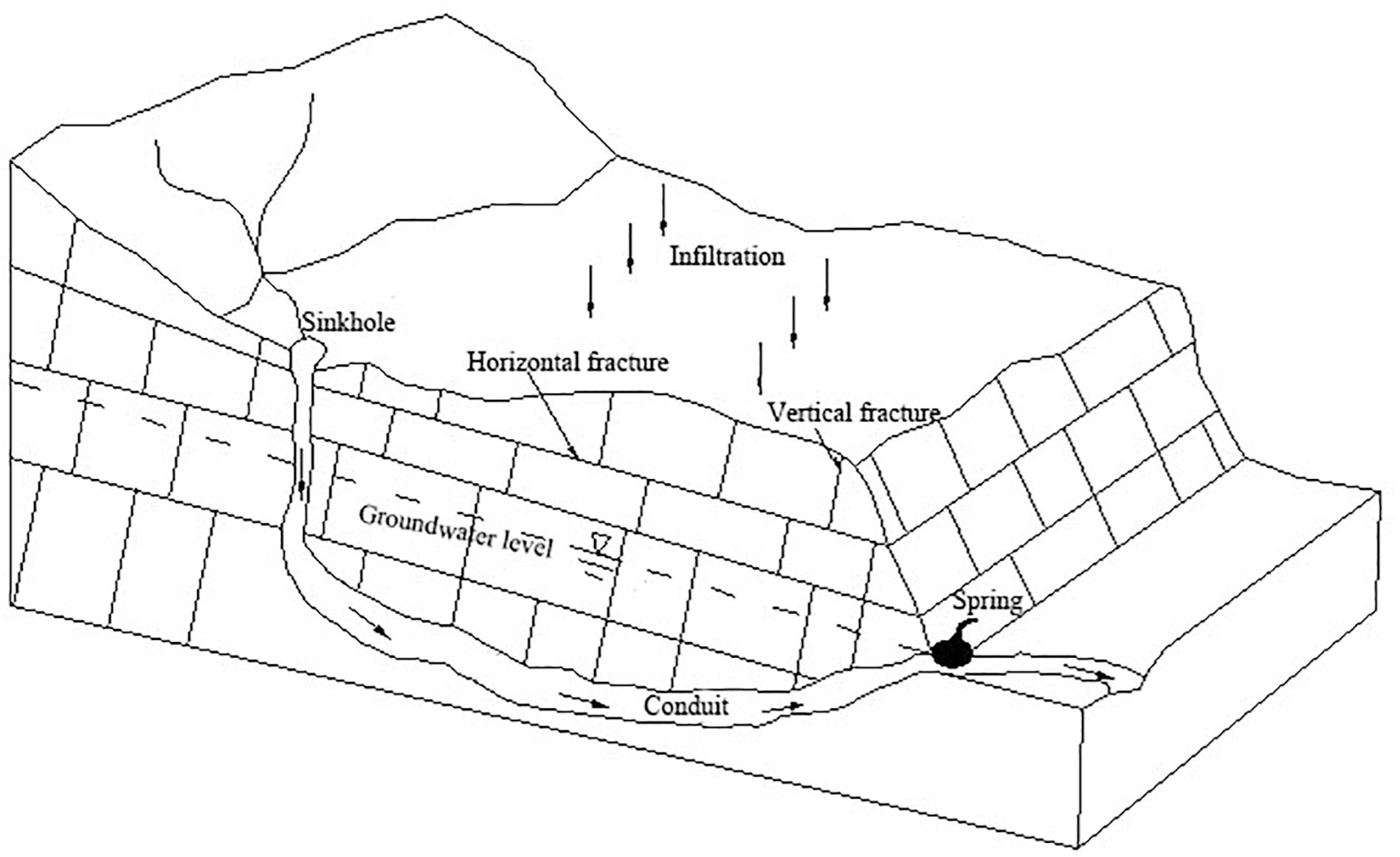
Figure 1. A water cycle in karst aquifer system (adapted from Figure 1.1, Goldscheider and Drew, 2007).
Based on the above described water cycle, we set up a laboratory analog to simulate groundwater flow with conduit-fissure medium in karst aquifers (Figure 2). The analog has two domains. The fissure network is formed with series of parallel glass blocks. The permeability of the fissure network is determined by the distance from two parallel glass blocks. The interior of the matrix measures 129cm × 80cm × 3cm. The reserved place at the bottom of the experimental setup forms a conduit structure and the interior measures 129cm × 3cm × 3cm. A constant-head upstream reservoir is connected to the recharge flume at the top of the experimental apparatus. Water flowed into the system from the supply reservoir and is divided into two kinds of paths by the inlet control valves, one flow into the vertical conduit as the main source of supply to conduit; the other flow into the fissure network. The exhaust valve is used to remove the trapped air. A flowmeter is placed at the end of the horizontal conduit to measure the spring discharge. There are 25 ports available for pressure transducers to measurements of hydraulic pressure The conduit has one inflow and one outflow as well as 4 ports for pressure sensors. The fissure network domain has one inflow and the discharge is drained through the conduit, with 21 water pressure sensors. In this setup, the ratio of conduit number to fracture number is 26:1,and the volume of conduit to fracture is 0.73. Table 1 showed the numbers and size of conduit and fissure.
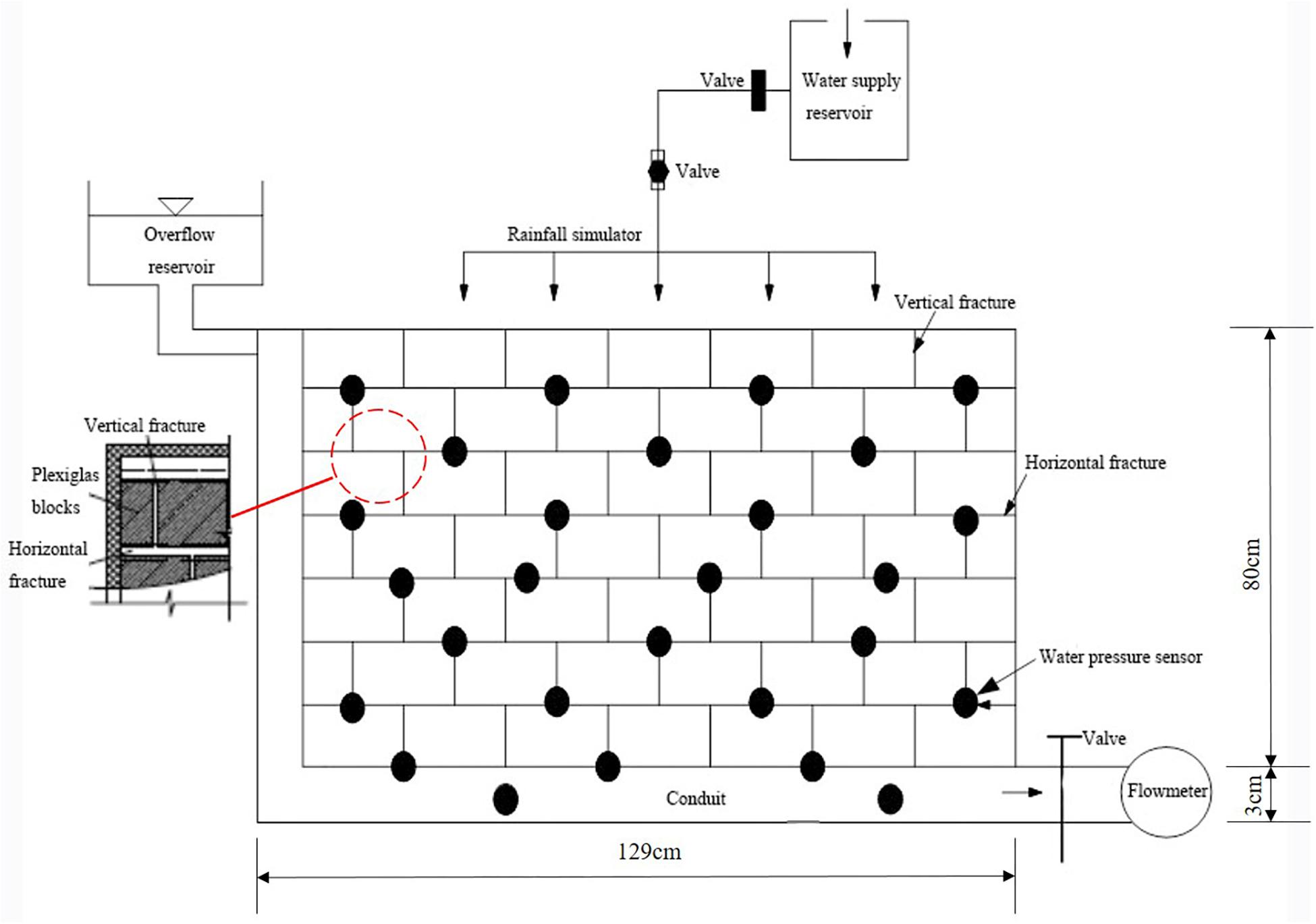
Figure 2. Schematic diagram of the laboratory analog setup.
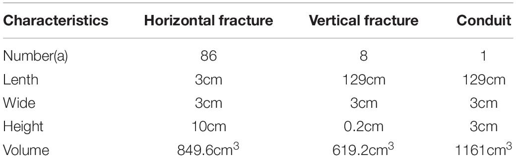
Table 1. The numbers and size of fissure and conduit.
Water flowed in from the water supply reservoir and flowed out from the outlet tube. The karst water flow was simulated by the laboratory analog under different infiltration recharge values and measured by the outlet flowmeter. Low infiltration recharge condition was simulated by the inlet valves open at 1/2 place, and high infiltration recharge condition was simulated by the inlet valves open at the maximum place. The data from the pressure transducers and the flowmeter are recorded when both the discharge of the output and the water level of the recharge flume are in a steady state controlled by the inlet and outlet valves. Experiments are repeated twice for the same laboratory setup to ensure the accuracy of the measurement.
Base on the laboratory analog, we develop a numerical model to simulate groundwater flow in a karst aquifer by multifield physical coupling finite element numerical method coupling Darcy’ law and Navier-Stokes equations. Take the bottom of the model as the base level, and z is the distance from the base level. Flow moves from z = 0.83 m within a recharge flume and exits to the right side of the horizontal conduit. The fluid flow follows the Darcy’s law in the field for 0.03 m < z < 0.83 m. The Navier-Stokes equation governs flow from the conduit casing at the 0 < z < 0.03 m. The interface between the Darcy and N-S equation flow zone occurs at z = 0.03 m.
Figure 3 shows the experimental and simulated distributions of the hydraulic head varied with z under low recharge condition with the recharge quantity equal to 0.015 m3/s. Figure 4 shows the experimental and simulated distributions of the hydraulic head varied with z under high recharge condition with the recharge quantity equal to 0.03 m3/s. Both Figures 3, 4 show a good agreement between the experimental results and the simulation results. The results present a plausible argument that the simulation results can characterize karst groundwater flow. According to the experimental and numerical results, it can be determined that the average hydraulic conductivity of the simulate fractured medium is 0.20m/s.
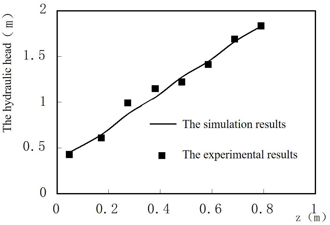
Figure 3. The hydraulic head distributions with z under low recharge condition.
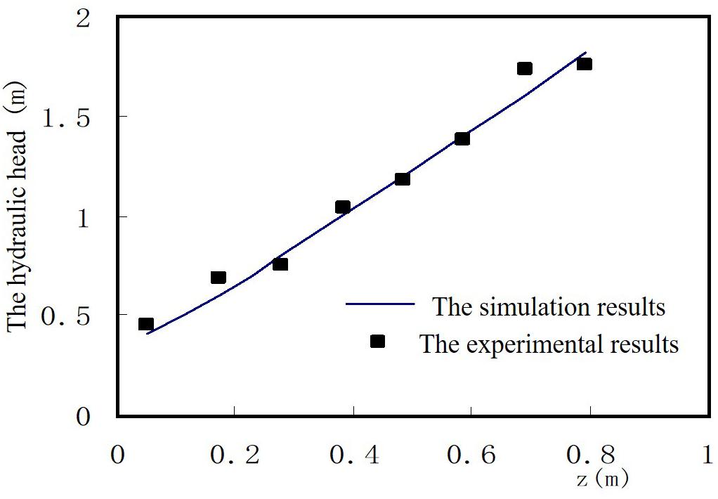
Figure 4. The hydraulic head distributions with z under high recharge condition.
The estimation of hydraulic conductivity in a karst aquifer is still a complex problem for the dimension-dependence behavior. In this study, different numerical simulations were carried out to investigate the effects of the dimension factors (the conduit diameter, fissure aperture and the strata dip angle) on the average hydraulic conductivity by identifying the relationship between the flow velocity and the hydraulic conductivity. The initial hydraulic pressure was also considering as another factor because it is an input parameter in the numerical simulation model.
The orthogonal method was used to construct an experiment plan shown in Table 2. Each factor has four values. According to the orthogonal table, 16 groups of numerical simulations experiments were taken under different factor values. The simulation results were shown in Table 3.
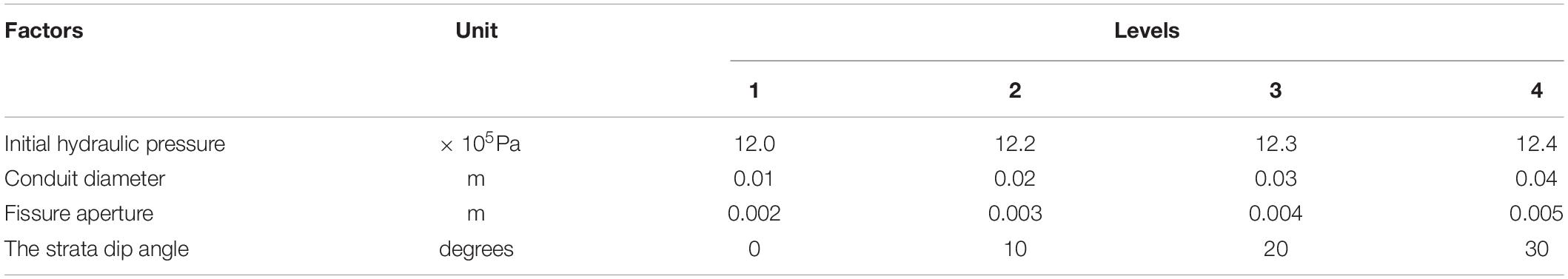
Table 2. The effect factors and levels of the orthogonal array design.
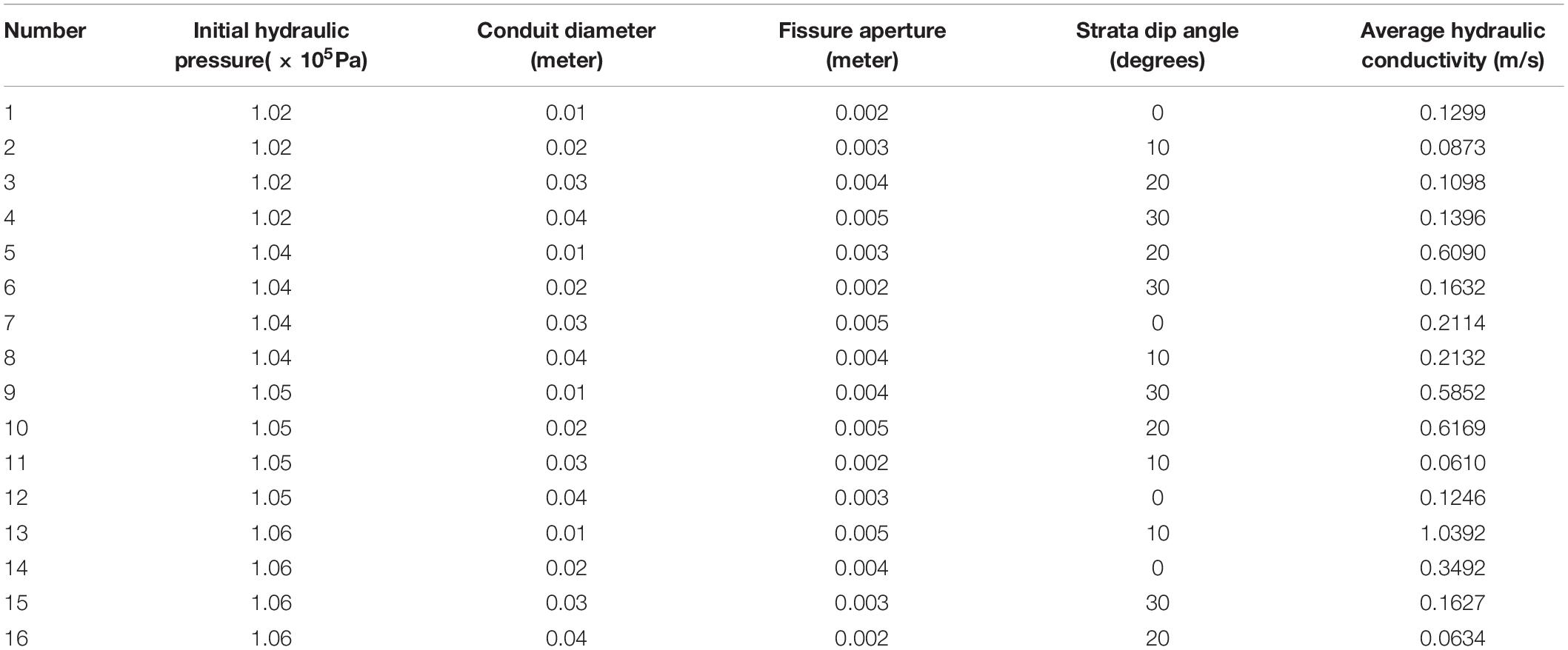
Table 3. The results of 16 group simulation experiments.
Variance analysis of the simulation experiment results were carried out shown in Table 4. According to F-test, when F > Fa = 0.05 = 9.28, the reliability of F-test was 95%, and when F > Fa = 0.1 = 5.39, the reliability of the test was 90%. The higher the confidence interval, the more significant the effect of this factor on the index. According to Table 4, it can be seen that the conduit diameter has the most significant influence on the average hydraulic conductivity, followed by the fissure aperture whose confidence interval reaches above 95%. In addition, the confidence interval of the initial hydraulic pressure value reaches 90%, while the strata dip angle has the least impact on the average hydraulic conductivity. Range represents the maximum amplitude of factor swings at different levels. The larger the range, the more obvious effect of the factor on the index. As can be seen from Table 4, conduit diameter and fissure aperture have great influence on the average hydraulic conductivity, followed by the initial hydraulic pressure and strata dip angle.
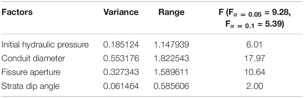
Table 4. Statistical analysis the simulation experiment results.
It is necessary to understand how these factors influence the average hydraulic conductivity by the numerical models which can deriving the relationship between the average hydraulic conductivity and outflow velocity when varying one of the input factor variable values at a time and holding all other input factor variable values constant. Numerical simulations will be performed under three different conditions.
First, the numerical model was used to simulate the velocity value of outlet flow under different initial hydraulic pressure values when holding other input factors values constant. In the calculation process, the water pressure is converted into the hydraulic head through the formula which is described as follws:
Where △H is the hydraulic head difference between the inflow and the outflow; z1 and z0 are the water head of inflow and outflow, respectively; P1 and P0 are the water pressure of inflow and outflow, respectively; u1 and u0 are the water velocity of inflow and outflow, respectively; J is the hydraulic gradient; L is the transmitting distance of the flow.
The input conduit diameter value of the model was set as 0.02 m, the fissure aperture as 0.004 m and the strata dip angle of the model as 0 degree while the initial hydraulic pressure value of the inlet was changing range from 1.015 × 10⁵Pa to 1.15 × 10⁵Pa. The pressure value of the outlet flow of the model was 1.013 × 10⁵Pa. The simulation results were presented in Table 5. It is interesting that the strata dip angle value was not hold as the constant input value but variable values varying with the initial hydraulic pressure seen from Table 5. It can presume that the change of the initial hydraulic pressure is due to the strata dip angle variable value. However, it can’t make more obvious impact on the average hydraulic conductivity only changing the strata dip angle values while holding the initial hydraulic pressure constant.
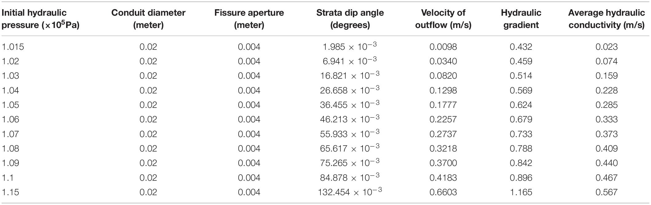
Table 5. The simulation results while varying the initial hydraulic pressure values.
As seen from Table 5, the outflow velocity values and the average hydraulic conductivity values increase gradually with the increase of hydraulic gradient. Figure 5 shows the linear relationship between the outflow velocity and the hydraulic gradient which obeys Darcy’ law. The relationship between the average hydraulic conductivity and pressure gradient was shown in Figure 6 and was fitted as a power function equation that
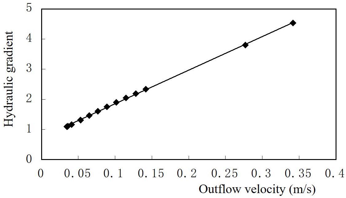
Figure 5. The relationship diagram between the outflow velocity and the hydraulic gradient.
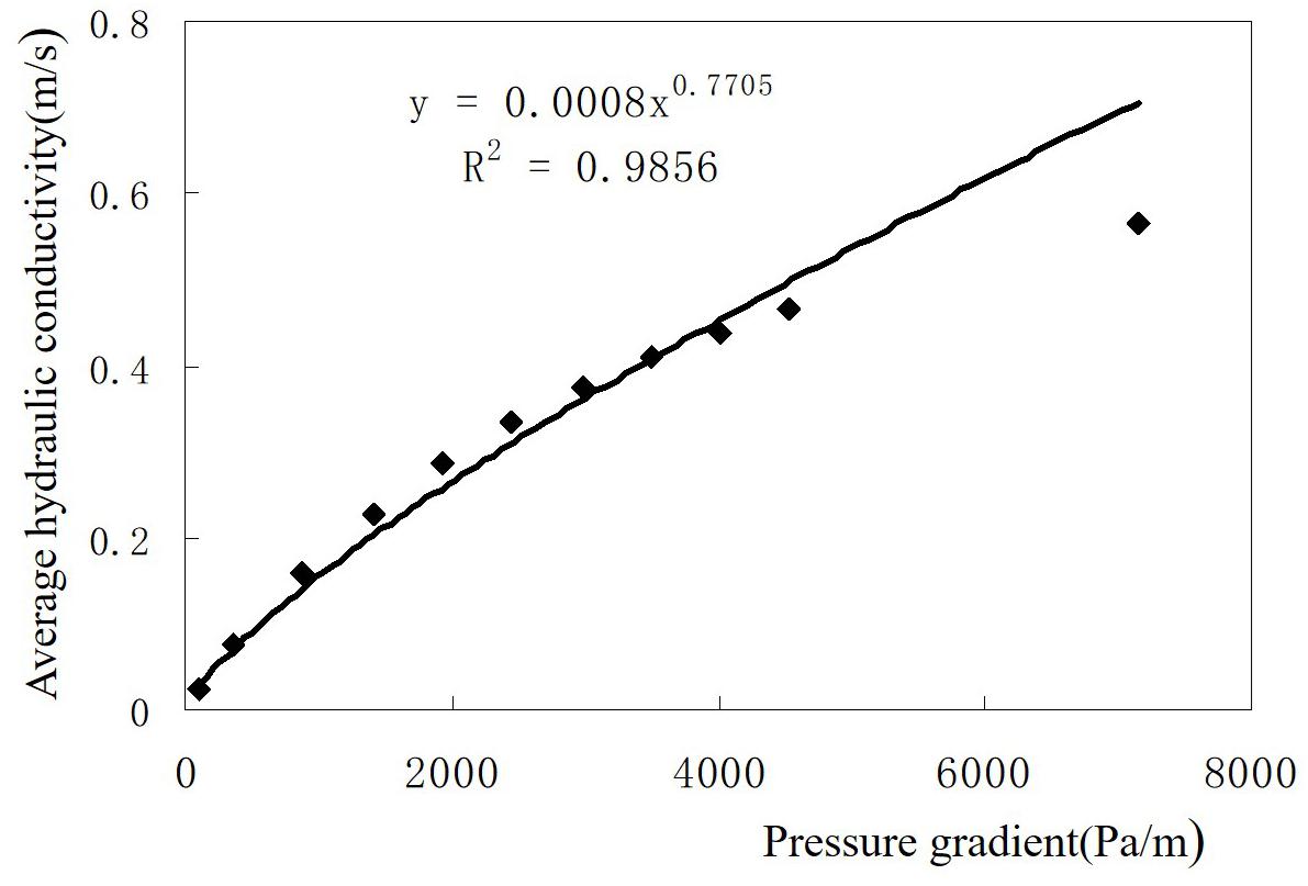
Figure 6. The relationship diagram between the average hydraulic conductivity and pressure gradient.
Where K is the average hydraulic conductivity and J is the hydraulic pressure gradient.
Second, the numerical model was used to simulate the velocity value of outlet flow under different conduit diameter values when initial hydraulic pressure was set as 1.04 × 10⁵Pa, fissure aperture as 0.004m and the strata dip angle as 0 degree. The flow velocity decreases with the increase of conduit diameter under the condition of the fixed fissure aperture value and initial hydraulic pressure value because of the increasing cross section of the conduit in the steady flow state from the numerical simulation results presented in Table 6. Moreover, the average hydraulic conductivity also decreased with the increase of conduit diameter. The relationship between the average hydraulic conductivity and conduit diameter was fitted shown in Figure 7 and is expressed as a power function as follows:
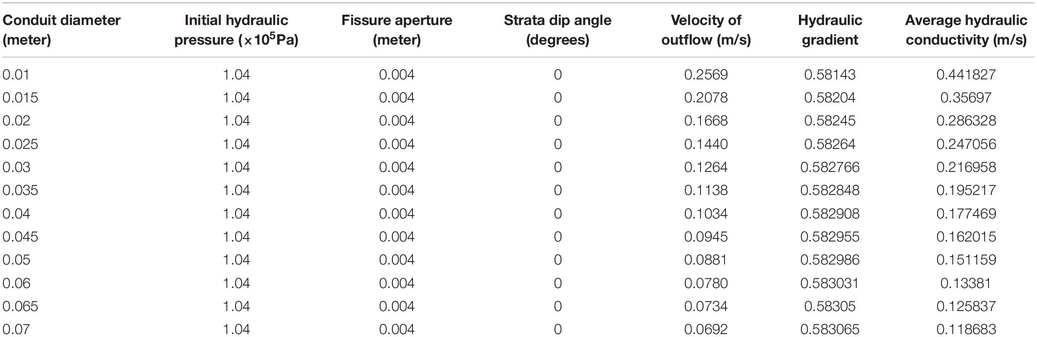
Table 6. The simulation results while varying conduit diameter.
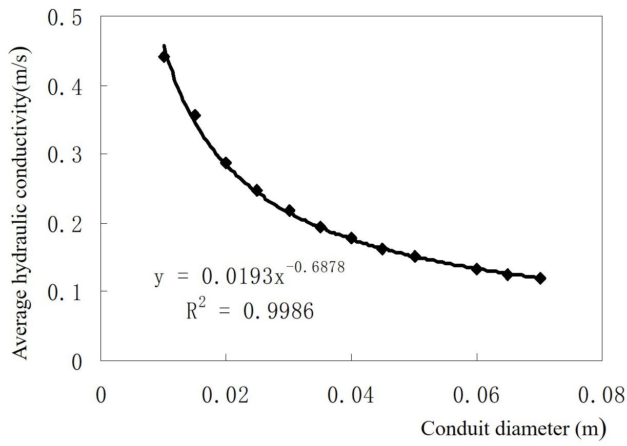
Figure 7. The relationship diagram between the average hydraulic conductivity and conduit diameter.
Where K is the average hydraulic conductivity and d is the conduit diameter.
Third, the numerical model was used to simulate the velocity value of outlet flow under different fissure aperture values when holding other input factors values constant. As seen from Table 7, the average hydraulic conductivity increases with the increase of fissure aperture. The relationship between the average hydraulic conductivity and fissure aperture is approximately linear trend expressed as
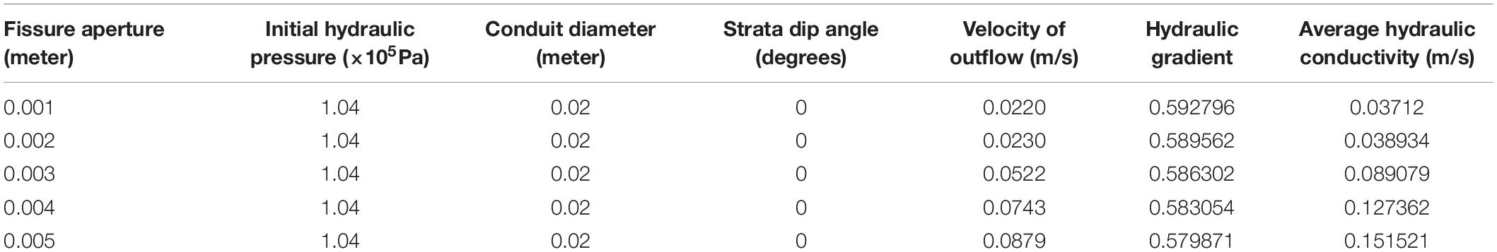
Table 7. The simulation results while varying fissure aperture.
Where K is the average hydraulic conductivity and b is the fissure aperture (see Figure 8).
Figure 8. The relationship diagram between the average hydraulic conductivity and fissure aperture.
According to the results of the three numerical simulation models and each relationship between the average hydraulic conductivity and its factors, an empirical equation was proposed to derive the hydraulic conductivity defined as :
Where K is the average hydraulic conductivity, J is the hydraulic pressure gradient, d is the conduit diameter and b is the fissure aperture.
This equation only applies to the similar medium and boundary conditions of above models under steady flow state.
This study developed a laboratory analog to simulate groundwater flow in a karst aquifer with one conduit in a fissure media. Several experiments were carried out to simulate groundwater flow with different infiltration recharge conditions providing hydraulic head distribution and spring discharges. The results from these experiments were used to verify and validate the following mathematical and numerical models. The mathematical and numerical models were also developed to simulate groundwater flow in a karst aquifer by coupling Darcy system with Navier-Stokes systems. The Darcy equation is adopted to describe flows in the fissure and the Navier-Stokes equations are used to describe flows in the conduit. The hydraulic responses from numerical simulation models show the similar trends with the laboratory experiments results.
Furthermore, numerical simulations were carried out to investigate the impacts of the dimension factors (the conduit diameter, fissure aperture and the strata dip angle) and the initial hydraulic pressure on the average hydraulic conductivity. Each relationship between the average hydraulic conductivity and its factors were expressed by fitted equations. The results showed that the dimension factors (the conduit diameter and fracture aperture) have the most influence on the hydraulic conductivity. And a new empirical equation was proposed to derive the hydraulic conductivity under the hydrogeological conditions set by the numerical models. It can contribute to improving knowledge about the behavior of such complex hydrological systems because it enables one to take into account the role of the dimension factors.
The datasets generated for this study are available on request to the corresponding author.
All authors listed have made a substantial, direct and intellectual contribution to the work, and approved it for publication.
This research work was funded by the National Natural Science Foundation of China (51774107), the Open Program of State Key Laboratory of Explosion Science and Technology (Beijing Institute of Technology) (KFJJ19-02M), and the Fundamental Research Funds of the Housing and Construction Department of Anhui Province (2013YF-27).
The authors declare that the research was conducted in the absence of any commercial or financial relationships that could be construed as a potential conflict of interest.
Arbogast, T., and Brunson, D. S. (2007). A computational method for approximating a darcy–stokes system governing a vuggy porous medium. Comput. Geosci. 11, 207–218. doi: 10.1007/s10596-007-9043-0
Arbogast, T., and Lehr, H. L. (2006). Homogenization of a darcy-stokes system modeling vuggy porous media. Comput. Geosci. 10, 291–302. doi: 10.1007/s10596-006-9024-8
Bailly-Comte, V., Martin, J. B., Jourde, H., Screaton, E. J., and Pistre, S. (2010). Water exchange and pressure transfer between conduits and matrix and their influence on hydrodynamics of two karst aquifers with sinking streams. J. Hydrol. 386, 55–66. doi: 10.1016/j.jhydrol.2010.03.005
Burman, E., and Hansbo, P. (2005). Stabilized crouzeix-raviart element for the darcy–stokes problem. Numer. Methods Partial Differ. Equ. 21, 986–997. doi: 10.1002/num.20076
Burman, E., and Hansbo, P. (2007). A unified stabilized method for stokes and Darcy equations. J. Comput. Appl. Math. 198, 35–51. doi: 10.1016/j.cam.2005.11.022
Cao, Y., Gunzburger, M., Hu, X., Hua, F., Wang, X., and Zhao, W. (2010a). Finite element approximations for Stokes–darcy flow with beavers–joseph interface conditions. SIAM J. Numer. Anal. 47, 4239–4256. doi: 10.1137/080731542
Cao, Y., Gunzburger, M., Hua, F., and Wang, X. (2010b). Coupled stokes-darcy model with Beavers–Joseph interface boundary condition. Commun. Math. Sci. 8, 1–25. doi: 10.4310/cms.2010.v8.n1.a2
Chen, C. X. (1995). Groundwater flow model and simulation method in triple karst tube-fissure-pore (in Chinese). Earth Sci. 20, 361–366.
Cheng, C., and Chen, X. (2007). Evaluation of methods for determination of hydraulic properties in an aquifer–aquitard system hydrologically connected to river. Hydrogeol. J. 15, 669–678. doi: 10.1007/s10040-006-0135-z
Cheng, J. M., and Chen, C. X. (2005). An integrated linear/non-linear flow model for the conduit-fissure-pore media in the karst triple void aquifer system. Environ. Geol. 47, 163–174. doi: 10.1007/s00254-004-1128-7
Faulkner, J., Hu, B. X., Kish, S., and Hua, F. (2009). Laboratory analog and numerical study of groundwater flow and solute transport in a karst aquifer with conduit and matrix domains. J. Contam. Hydrol. 110, 34–44. doi: 10.1016/j.jconhyd.2009.08.004
Goldscheider, N., and Drew, D. (2007). Methods in Karst Hydrogeology IAH: International Contributions to Hydrogeology, 26. Boca Raton, FL: Crc Press.
Hartmann, A., Goldscheider, N., Wagener, T., Jens, L., and Markus, W. (2014). Karst water resources in a changing world: review of hydrological modeling approaches. Rev. Geophys. 52, 218–242. doi: 10.1002/2013rg000443
Huang, Z., Jiang, Z., Zhu, S., Wu, X., and Yang, L. (2016). Influence of structure and water pressure on the hydraulic conductivity of the rock mass around underground excavations. Eng. Geol. 202, 74–84. doi: 10.1016/j.enggeo.2016.01.003
Li, G., Loper, D. E., and Kung, R. (2007). Laboratory simulation of solute transport and retention in a Karstic aquifer. Water Resour. Res. 44:W02429.
Lin, H., Yang, H. T., Wang, Y. X., Zhao, Y. L., and Cao, R. H. (2019). Determination of the stress field and crack initiation angle of an open flaw tip under uniaxial compression. Theor. Appl. Fract. Mech. 104:102358. doi: 10.1016/j.tafmec.2019.102358
Loper, D. E., and Eltayeb, I. A. (2008). On the relation between excess hydraulic head and flow in a conduit imbedded within a porous matrix. Geophys. Astrophys. Fluid Dyn. 102, 281–297. doi: 10.1080/03091920701806385
Mangiarotti, S., Sekhar, M., Berthon, L., Javeed, Y., and Mazzega, P. (2012). Causality analysis of groundwater dynamics based on a vector autoregressive model in the semi-arid basin of Guidal (South India). J. Appl. Geophys. 83, 1–10. doi: 10.1016/j.jappgeo.2012.04.003
Mangiarotti, S., Zhang, Y., and Leblanc, M. (2019). Chaos theory applied to the modelling of karst springs: first results from univariate time series. Hydrogeol. J. 27, 2007–2043.
Martin, J. B., and Dean, R. W. (2001). Exchange of water between conduits and matrix in the Floridan aquifer. Chem. Geol. 179, 145–165. doi: 10.1016/s0009-2541(01)00320-5
Mas Ivars, D. (2006). Water inflow into excavations in fractured rock–a three-dimensional hydro-mechanical numerical study. Int. J. Rock Mech. Min. Sci. 43, 705–725. doi: 10.1016/j.ijrmms.2005.11.009
Mohrlok, U., and Teutsch, G. (1997). “Double continuum porous equivalent (DCPE) versus discrete modelling in karst terranes,” in Proceedings 5th International symposium and field seminar on karst waters and environmental impacts, Antalya.
Peterson, E. W., and Wicks, C. M. (2005). Fluid and solute transport from a conduit to the matrix in a carbonate aquifer system. Math. Geol. 37, 851–868.
White, W. B. (2002). Karst hydrology: recent developments and open questions. Eng. Geol. 65, 85–105. doi: 10.1016/s0013-7952(01)00116-8
White, W. B., and White, E. L. (2005). Ground water flux distribution between matrix, fractures, and conduits: constraints on modeling. Speleogen. Evol. Karst Aquif. 3, 1–6.
Zhao, Y. L., Luo, S. L., Wang, Y. X., Wang, W. J., Zhang, L. Y., et al. (2017). Numerical analysis of karst water inrush and a criterion for establishing the width of water-resistant rock pillars. Mine Water Environ. 36, 508–519. doi: 10.1007/s10230-017-0438-4
Zhao, Y. L., Wang, Y. X., and Tang, L. (2019a). The compressive-shear fracture strength of rock containing water based on druker-prager failure criterion. Arab. J. Geosci. 12:452.
Keywords: Karst aquifer, hydraulic conductivity, conduit-fissure medium, numerical model, laboratory analog
Citation: Li X, Ke T, Wang Y, Zhou T, Li D, Tong F and Wen J (2020) Hydraulic Conductivity Behaviors of Karst Aquifer With Conduit-Fissure Geomaterials. Front. Earth Sci. 8:30. doi: 10.3389/feart.2020.00030
Received: 11 December 2019; Accepted: 27 January 2020;
Published: 18 February 2020.
Edited by:
Yanlin Zhao, Hunan University of Science and Technology, ChinaReviewed by:
Wen Nie, Shandong University of Science and Technology, ChinaCopyright © 2020 Li, Ke, Wang, Zhou, Li, Tong and Wen. This is an open-access article distributed under the terms of the Creative Commons Attribution License (CC BY). The use, distribution or reproduction in other forums is permitted, provided the original author(s) and the copyright owner(s) are credited and that the original publication in this journal is cited, in accordance with accepted academic practice. No use, distribution or reproduction is permitted which does not comply with these terms.
*Correspondence: Yanqiao Wang, d2FuZ3lxMDcyNkAxNjMuY29t; Tingguo Zhou, MTI5NjA5NTA5N0BxcS5jb20=
†These authors share first authorship
Disclaimer: All claims expressed in this article are solely those of the authors and do not necessarily represent those of their affiliated organizations, or those of the publisher, the editors and the reviewers. Any product that may be evaluated in this article or claim that may be made by its manufacturer is not guaranteed or endorsed by the publisher.
Research integrity at Frontiers
Learn more about the work of our research integrity team to safeguard the quality of each article we publish.