Long-term neural recordings using MEMS based movable microelectrodes in the brain
- 1 School of Biological and Health Systems Engineering, Arizona State University, Tempe, AZ, USA
- 2 Micro Electro Mechanical Systems Science and Technology Division, Sandia National Laboratories, Albuquerque, NM, USA
One of the critical requirements of the emerging class of neural prosthetic devices is to maintain good quality neural recordings over long time periods. We report here a novel MEMS (Micro Electro Mechanical Systems) based technology that can move microelectrodes in the event of deterioration in neural signal to sample a new set of neurons. Microscale electro-thermal actuators are used to controllably move microelectrodes post-implantation in steps of approximately 9 μm. In this study, a total of 12 movable microelectrode chips were individually implanted in adult rats. Two of the twelve movable microelectrode chips were not moved over a period of 3 weeks and were treated as control experiments. During the first 3 weeks of implantation, moving the microelectrodes led to an improvement in the average signal to noise ratio (SNR) from 14.61 ± 5.21 dB before movement to 18.13 ± 4.99 dB after movement across all microelectrodes and all days. However, the average root-mean-square values of noise amplitudes were similar at 2.98 ± 1.22 μV and 3.01 ± 1.16 μV before and after microelectrode movement. Beyond 3 weeks, the primary observed failure mode was biological rejection of the PMMA (dental cement) based skull mount resulting in the device loosening and eventually falling from the skull. Additionally, the average SNR for functioning devices beyond 3 weeks was 11.88 ± 2.02 dB before microelectrode movement and was significantly different (p < 0.01) from the average SNR of 13.34 ± 0.919 dB after movement. The results of this study demonstrate that MEMS based technologies can move microelectrodes in rodent brains in long-term experiments resulting in improvements in signal quality. Further improvements in packaging and surgical techniques will potentially enable movable microelectrodes to record cortical neuronal activity in chronic experiments.
Introduction
One of the most commonly used implants for the brain is the microelectrode that is used to either record or stimulate single neurons or neuronal networks in the brain. Long-term functionality of the microelectrode implants in the brain is critical for the success of emerging applications in cortical neural prostheses and other long-term neurobiology studies on the progression of disease states, learning and memory, development of neuronal networks etc. However, current microelectrode technologies are inconsistent in their performance and unreliable in long-term experiments. Multi-unit recordings obtained from current fixed microelectrode technologies typically show deterioration in signal quality with time and almost all of them fail over periods ranging from few weeks to few years. Further, the same microelectrode technology can often yield successful multi-unit recordings for widely varying durations of time before they fail.
Several studies have investigated the use of movable microelectrodes (Reitboeck, 1983 ; Wilson and McNaughton, 1993 ; Fee and Leonardo, 2001 ; Cham et al., 2005 ; Muthuswamy et al., 2005a ,b ; Venkateswaran et al., 2005 ; Jackson and Fetz, 2007 ; Sato et al., 2007 ; Yamamoto and Wilson, 2008 ) to improve the consistency of multi-unit recordings and also to seek specific neuronal targets. Movable microelectrodes offer many advantages over traditional stationary microelectrodes. They have the potential capability of moving past the glial sheath surrounding the microelectrodes to restore the electrical interface with functional neurons in long-term experiments. Further, in short-term experiments, the microelectrodes can be moved to counter the variabilities in signal amplitudes due to brain motion caused either by animal behavior, or other endogenous factors. They also have the potential ability to track neurons or groups of neurons, and can be useful in locating specific targets in the brain. In addition, in the event of a failure in electrical recordings due to any number of reasons indicated earlier, one could potentially move the microelectrodes to a new location and re-establish electrical connectivity with another neuron located in the same vertical axis as the neuron before. The first generation of movable microelectrodes used manually movable microwire electrodes (Wilson and McNaughton, 1993 ; Jackson and Fetz, 2007 ) in chronic experiments. However, the manual movement of these microelectrodes requires constant supervision making it cumbersome. Subsequently, the first motorized movable microelectrodes used DC motors to move the microelectrodes (Fee and Leonardo, 2001 ; Venkateswaran et al., 2005 ). More recently, there have been several attempts at using piezoelectric motors (Cham et al., 2005 ; Park et al., 2008 ), servomotors (Yamamoto and Wilson, 2008 ), and hydraulic motors (Sato et al., 2007 ) to move microelectrodes in the brain. However, the size and weight of these devices are often large. There is therefore a need to reduce the size and weight of movable microelectrodes while automating their ability to move within the brain after implantation in order to produce a potential chronic neural interface. A MEMS based movable microelectrode device can allow for batch fabrication, integration with advanced signal conditioning circuitry such as signal processors and wireless transmission and ensure the integrity of the interconnects. The goal of this study is to validate a MEMS based movable microelectrode array in long-term rodent experiments. While the technology presented here is potentially capable of countering the variabilities in the signal amplitude over a period of hours in short-term experiments, testing for that capability is not the goal of this study. This study is primarily focused on testing the durability of the single-neuronal data from MEMS based movable microelectrodes.
We have developed two different implantable microtechnologies based on micro electro mechanical systems (MEMS) to meet the need for small, lightweight, movable microelectrodes capable of autonomous movement within the brain and recording multi-unit activity in acute rodent experiments (Muthuswamy et al., 2005a ,b ). Our most recent MEMS based movable microelectrode arrays use electro-thermal actuators to allow bi-directional movement post-implant by applying low-voltage square pulses. Using the SUMMiT V™ (Sandia Ultra-planar Multi-level MEMS Technology 5, with 5-layers of polysilicon) process, three polysilicon microelectrodes, whose movements are controlled by electro-thermal actuators were surface micromachined on each chip. The overall dimensions of each of the microelectrodes are 50 μm × 4 μm × 5 mm. The microelectrodes are spaced by ∼800 μm within the chip. The overall dimensions of the entire chip are 3 mm × 600 μm × 6 mm. Micrographs and SEM images of the MEMS movable microelectrode devices are shown in Figure 1 .
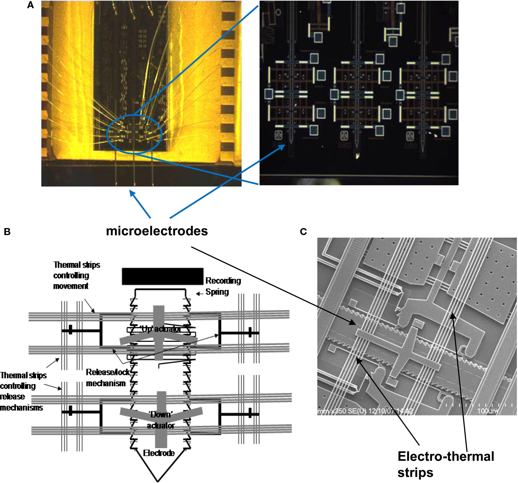
Figure 1. (A) Micrograph of the movable microelectrode chip wire bonded on the chip carrier showing the three microelectrodes extended out at the bottom of the chip. The picture on the right shows a closer view of the bottom of the microchip with the microelectrodes and microactuators. (B) Schematic of a single polysilicon microelectrode and the associated thermal-microactuators/electro-thermal strips (chip is 3-mm wide and 6-mm long). (C) SEM of the middle microelectrode (50-μm wide) and the associated electro-thermal strips, and ratchets that move the microelectrodes. The device is externally controlled by application of voltage pulses via the labeled bond pads.
Materials and Methods
Principle of Electro-Thermal Actuators
The principle of the electro-thermal actuators is illustrated in Figure 2 . Each of the microelectrodes has six bond pads connected to an external OmneticsTM connector, by which the microelectrode can be controllably moved and used to record multi-unit activity. Each microelectrode is controlled by four microactuators (Figure 2 A) – one each to deactivate the release-up lock and release-down lock, and one each to move the microelectrode up and down. Briefly, the V-beam microactuators work by using electro-thermal strips, where the applied low-voltage pulse (7–10V) causes an increase in temperature and subsequent thermal expansion of the strips. Before the microelectrodes are moved up or down, the corresponding locks that prevent the microelectrode from moving are activated to release the microelectrode for motion (Figure 2 B). The microactuators are coupled to a ratcheting system that drives the center shuttle either down or up (Figure 2 C), depending on whether the move-up or the move-down microactuator is being activated respectively. As the applied voltage pulse is reduced to zero, the electro-thermal strips rapidly cool down and return to their normal position. During the return to their normal deactivated position (Figure 2 D), the center shuttle grabs the next adjacent teeth on the microelectrode and pulls it up or down depending on whether the move-up or the move-down microactuator is activated. Electro-thermal actuation mechanism allows for bi-directional movement with approximately 9 μm resolution in movement (equivalent to the spacing of the teeth on the side of the microelectrode). The reader is referred to our earlier report (Muthuswamy et al., 2005a ) for more information on the principle of actuation and fabrication of the array of movable microelectrodes. The aim of this study is to validate the array of movable microelectrodes in long-term rodent experiments and test if movable microelectrodes can improve the quality and reliability of neuronal recordings from the cortical brain region of rats.
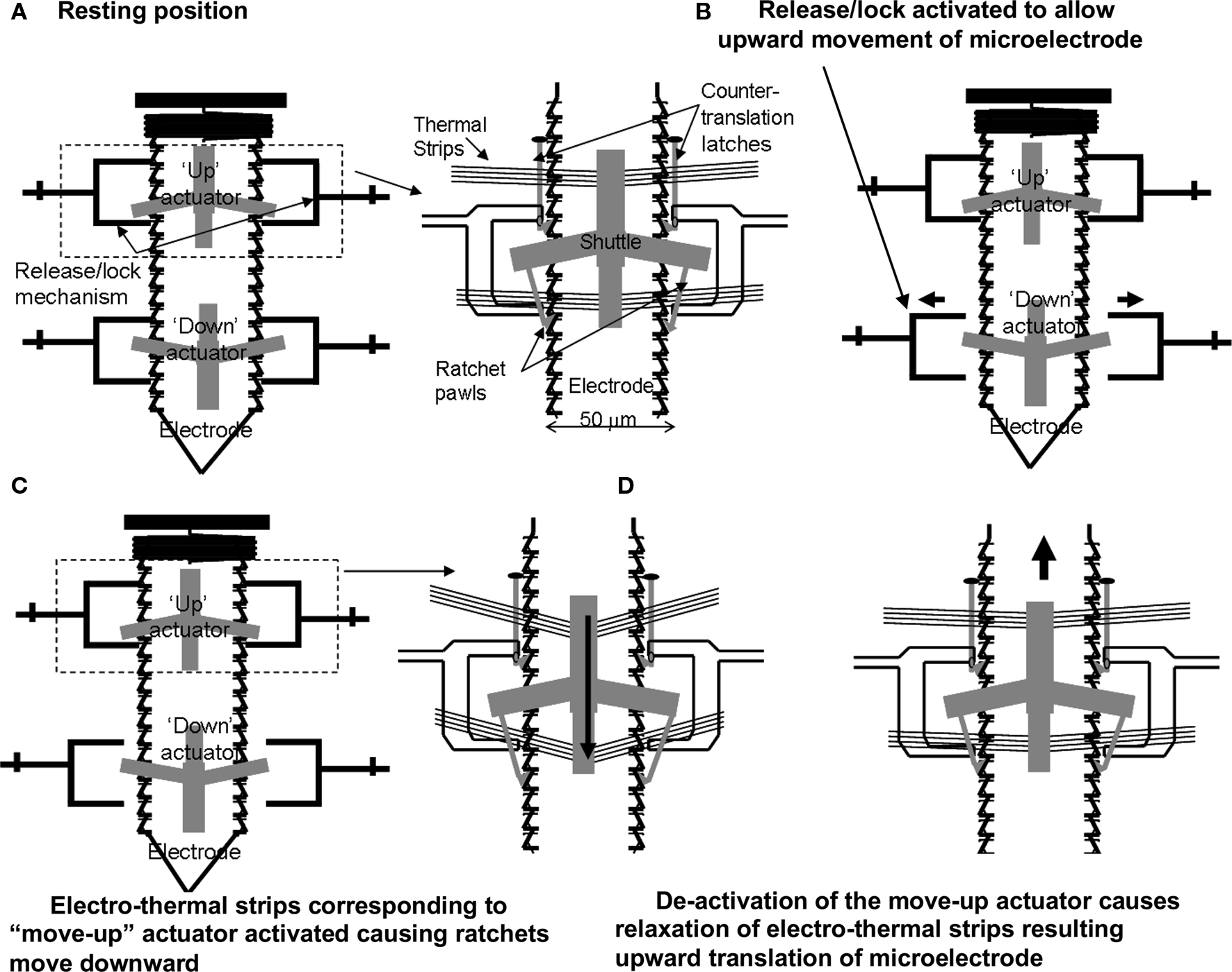
Figure 2. A schematic showing the principle of the electro-thermal actuators and how they move a microelectrode bi-directionally. (A) Resting position. (B) Release/lock activated to allow upward movement of microelectrode. (C) Electro-thermal strips corresponding to “move-up” actuator activated causing ratchets to move downward. (D) De-activation of the move-up actuator causes relaxation of electro-thermal strips resulting upward translation of microelectrode.
Fabrication of MEMS Device
A silicon wafer is used as a starting substrate for the MEMS device. All of the chips were fabricated using the SUMMiT VTM process at Sandia National Laboratories, Albuquerque, NM (Sniegowski and de Boer, 2000 ). The SUMMiT VTM process uses a five-layer polysilicon process with a sacrificial oxide layer that is deposited using low-pressure chemical vapor deposition (LPCVD) from tetraethylorthosilicate (TEOS) in between each polysilicon layer. The layers are planarized by using chemical-mechanical polishing (CMP). The microelectrodes are a combination of two or three polysilicon layers of different thicknesses, whereas the actuators, electro-thermal strips, ratchets, shuttle and other mechanical structures are defined in all five polysilicon layers. After micromachining the final layers, the devices are released using hydrofluoric (HF) acid, which removes the oxide layer. The polysilicon layers for the microelectrodes are highly doped (1021/cm3) with phosphorus (n-type), making the microelectrode conducting. The fabrication of the microelectrodes used in the MEMS based device is integrated with the fabrication of the microactuators in the SUMMiT VTM process, As stated above the microelectrodes consist of the polysilicon two and three layers. Variations of the electrode geometry can be accomplished by redesigning the masks.
Packaging of MEMS Device
The chip was bonded to a 40-pin chip carrier (Spectrum Semiconductor Materials, Inc., San Jose, CA, USA) using a non-conducting adhesive. The chip carrier was cut on one side prior to bonding in order to create an open cavity, which would allow the microelectrodes to extend off the edge of the chip. The MEMS device was then wire bonded to the chip carrier using gold wire. A glass cover was bonded to the top of the chip carrier in order to protect the device. The chip carrier was then bonded using surface mount techniques (SMT) to a custom made PCB that contained a 16-channel OmneticsTM connector (NPD-AA, Omnetics Corp., Minneapolis, Mn.) for connecting the headstage during recording sessions. Two stainless steel (316L) wires (50 μm diameter) were bonded to the PCB using conducting epoxy, which acted as the reference and ground electrodes. In order to prevent fluid or debris entry into the chip post-implantation we mounted a composite material consisting of silicone gel and nylon mesh to the open cavity area of the chip carrier (Jackson et al., 2009 ). This material helps prevent fluid from entering the chip and is soft enough to allow our microelectrodes to penetrate through with ease. Two of the devices were packaged without the mesh encapsulation material. The overall dimensions of the device are 14 mm × 17 mm × 3 mm. However, this can be reduced by using a smaller chip carrier. The overall weight of the device is ∼1.9 g. After the device had been completely packaged, the microelectrodes were extended down off the edge of the chip (2–3 mm). The microelectrodes were insulated by dip coating with epoxylite (48-1696 P.D. George Company., St. Louis, MO, USA) (Verhagen et al., 2003 ). The insulation was etched using an epoxy stripper (MS-111 Miller-Stephenson Inc., Sylmar, CA, USA) to create one recording site at the tip of each microelectrode. Approximately 1000 μm2 area was etched to create the recording site. The size of the etched recording site varied among microelectrodes due to variabilities in the dip coating and etching process; however control was maintained by monitoring the electro-chemical impedance spectra during and after etching. A hard bake process followed after the microelectrodes were etched (30 min at 199°C). The final thickness of the insulation varied slightly due to the dip coating process, but typical thicknesses were between 5–10 μm. A micrograph of the packaged device is shown in Figure 3 .
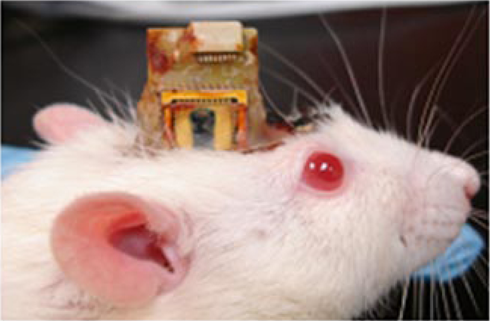
Figure 3. The packaged device implanted on a rat’s head. The chip itself is 3 mm × 6 mm (seen in black). The device is wire bonded to sawed-off chip carrier, and a glass cover is bonded for protection. The microelectrodes are extended off the chip and through the silicone gel encapsulation material. The whole device is bonded onto a custom made PCB with ground wires and Omnetics™ connectors (in white) on top.
Surgery
In order to validate the use of our movable microelectrode chip or device to obtain functional neural recordings under long-term experimental conditions we implanted a total of n = 12 Sprague-Dawley rats (including two control animals). Each device contained one or two functional microelectrodes since the third microelectrode was damaged in all 12 devices during the fabrication process. The control group consisted of two animals that were implanted for a period of 12 weeks in which the microelectrodes were not moved. The rats were approximately 300 g in weight prior to the start of the experiment. All animal procedures were carried out with the approval of the Institute of Animal Care and Use Committee (IACUC) of Arizona State University, Tempe. The experiments were performed in accordance with the National Institute of Health (NIH) guide for the care and use of laboratory animals (1996). All efforts were made to minimize animal suffering and to use only the number of animals necessary to produce reliable scientific data.
The animals were induced using a mixture of (50 mg/ml) ketamine, (5 mg/ml) xylazine, and (1 mg/ml) acepromazine administered intramuscularly with an initial dosage of 0.1 ml/100 g body weight. Throughout the surgery, updates were given as needed at a dose of 0.05 ml/100 g body weight. The anesthesia for update contained a mixture of 50 mg/ml ketamine and 5 mg/ml xylazine. The rat was attached to a stereotaxic frame (Kopf Instruments, Tujunga, CA, USA). After the skull was exposed, two stainless steel bone screws (19010-10 Fine Science Inc., Foster City, CA, USA) were screwed into the skull to act as anchors. Two small craniotomies (∼0.5 mm) were drilled for the reference and ground electrodes. A larger craniotomy (3 × 2 mm) was drilled with the center point being 2.5 mm lateral to the midline and 2.5 mm posterior to the bregma. After the bone chips were removed, the dura was carefully incised and pulled back away from the center of the craniotomy. The device was mounted on a micromanipulator using bees wax. The microelectrodes were slowly inserted into the brain at a rate of 10 μm/s. The microelectrodes were implanted to a depth of approximately 1 mm in order to record from the rodent somatosensory cortex. The reference and ground wires were manually inserted into the smaller craniotomies. After implantation, dental cement (PMMA) was used to secure the device to the skull.
Data Collection/Analysis
Neural recordings were obtained using a 16-bit multi-channel recording system (TDT Inc., Alachua, FL, USA). The rats were lightly sedated for the recording sessions. Recordings were taken 3–4 times a week for a period of 2–3 weeks. Each recording session contained three to five 1-min segments. Recordings from the control group were taken once a week for a period of 12 weeks. The neural signals were sampled at 12 kHz and bandpass filtered from 300–3000 Hz, with a gain of 10,000. The recording system was connected to the device via a headstage with matching OmneticsTM connector, which was then routed through an A/D converter. The animal was placed in shielded faraday cage to prevent any unwanted noise. Raw data and individual spikes were recorded. Spikes were sorted online by transferring any signal that was greater than three times the standard deviation of the amplitude distribution into a separate file, to be analyzed offline.
The spike waveforms were sorted offline using Offline Sorter (Plexon Inc., Dallas, TX, USA). The sorting technique used principle component analysis to sort the spikes into various signals or units. The continuous neural recordings were transferred into a custom made MatlabTM algorithm to determine signal to noise ratio (SNR), average signal amplitude (peak to peak), and the average noise amplitude. Signals were detected using an amplitude threshold of three times the standard deviation of the recorded signal. Amplitudes below this threshold were considered noise. The SNR was determined by the ratio of signal power to the noise power as shown below:
where sij is the signal data values of series j at the ith point, p is the total number of signal points, nij is the noise data values of series j at the ith point, and b is the total number of noise points. A SNR of 10 dB represents an average signal amplitude that is approximately three times larger than the average noise amplitude. The root-mean-square (RMS) value of the noise was calculated for duration of the experiment.
If the SNR was less than 10 dB, the microactuators were activated to move the microelectrodes either up or down in increments of 100 μm until a neuronal signal or unit activity was detected with SNR greater than 10 dB. The threshold of 10 dB was chosen since neuronal activity with SNR less than 10 dB was not visually perceptible in the recordings. Typically, the microelectrodes were moved up or down by 100 μm at a rate of (approximately 9 μm/s) until visually discernible signals were identified. The microelectrodes were moved either down or up depending on the current depth of the microelectrode tip below the cortical surface. The direction of the microelectrode movement (upward or downward) was randomized for each recording session to assess if there was a directional bias to the change in SNR in response to microelectrode movement and also to ensure that the microelectrode was in the same general vicinity as the original implant site. The microelectrodes were moved in 100 μm increments in order to potentially sample a different set of target neurons than the ones in the current position. In order to move the microelectrodes the headstage had to be removed and replaced with another connector to enable activation of the actuators. After the microelectrodes were moved, the headstage was replaced and recordings were taken. The overall time in between recordings was approximately 1 min, including switch time and time to activate the actuators.
Impedance Measurements
The impedance of each microelectrode was tested in vivo by a 3-electrode method using an electro-chemical workstation (CH Instruments Inc., Austin, TX, USA). The counter and reference electrode were both made of stainless steel wire similar to (Weiland and Anderson, 2000 ). A voltage was applied between the reference and the polysilicon microelectrode whereas current was measured between the counter and the polysilicon microelectrode. Voltages with amplitudes of 5 mV and frequencies between 100Hz–100 kHz were applied to each device and the impedance was measured. Two or three repeat impedance measurements were taken during each session. The value at 1 kHz was monitored over the period of the experiment in all of the microelectrodes (n = 14).
Results
This study included results from n = 12 MEMS based movable microelectrodes implanted in n = 10 rats and n = 2 stationary microelectrodes (control) implanted in two additional rats. Among the displacements produced in all the microelectrodes that were moved, the maximum cumulative distance travelled by a microelectrode was ∼700 μm (i.e., that particular microelectrode was moved seven times with a displacement of 100 μm each time either in the upward or downward direction). The maximum overall displacement from the initial position was 200 μm below the initial position. The average displacement of all the microelectrodes that were moved was 60 μm below the initial position.
Overall, device functionality and microelectrode mobility was maintained in 6 out of 8 of the devices that had the mesh encapsulation material to prevent fluid penetration into the device from the implant site. Both of the encapsulated devices that had fluid infiltration, labeled as device #1 and device #3 in Table 1 , showed failure at 14 days and at 89 days due to subsequent debris formation after dehydration of the fluids. Analysis of the failure mode after the experiment indicated that the mesh was improperly coated with silicone gel during the encapsulation process. All of the devices without the mesh encapsulation (devices# 9–12, including the two control devices in which the microelectrodes were not moved) failed due to the presence of fluids and subsequent solid debris on the devices. The two devices implanted without the mesh encapsulation and whose microelectrodes were moved failed at 9- and 14-days post-implantation. The other two control devices whose microelectrodes were not moved failed after ∼12 weeks. Of all devices, only one (device #4) showed total structural failure where most device components ceased to function after 49 days.
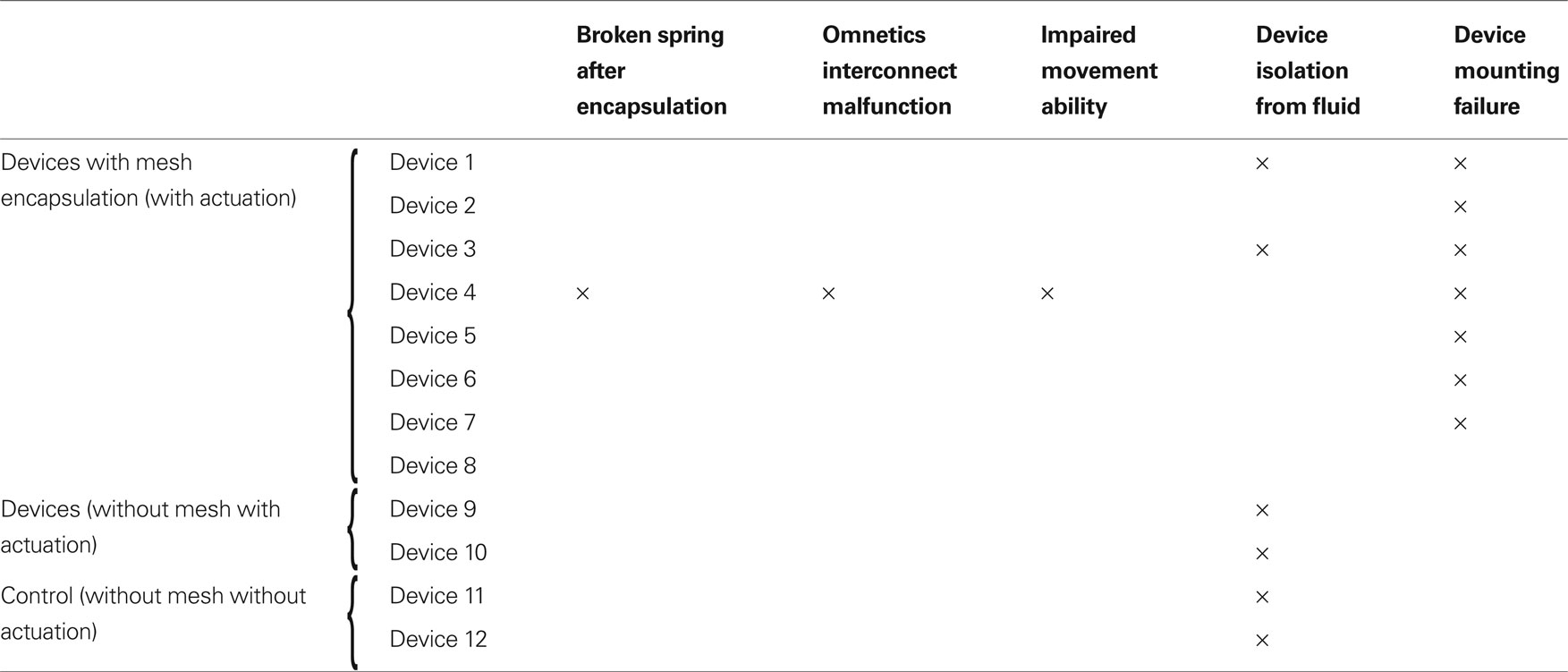
Table 1. Summary of observed failure modes.
Another observed failure mode that is particularly relevant in chronic long-term studies, was the tissue rejection of the dental cement based cranial mounting method. In all implanted animals, tissue penetrated underneath the dental cement as a wound-healing response and created a growing barrier that eventually popped the devices from the skull. In most cases, the tissue ingrowths imposed such a powerful structural stress that the entire implanted device popped off with the bone screws embedded in the dental cement and the skull. Such mounting failures occurred at varying time points in all eight mesh-encapsulated devices ranging from 30 days (in device #8) to 174 days (in device 4) post-implantation. Out of the eight devices which had mounting failure, five failed in the first 90 days, while three failed after 120 days. Therefore, the maximum life span of the current mounting technique using dental cement appears to range from ∼3–6 months.
Cortical Recordings
A brief recording segment of ∼3 s for both (a) before and (b) after microelectrode movement is shown in Figure 4 . The “before” segment shows the absence of any significant spiking activity. However, after actuation (microelectrode moved down ∼100 μm) a significant increase in spike activity with signal levels of ∼ 300 μV was seen. The noise levels on the other hand remain constant at ∼3-μV RMS. A typical recording segment with bursts of spike activity from day 83 is shown in Figure 5 .
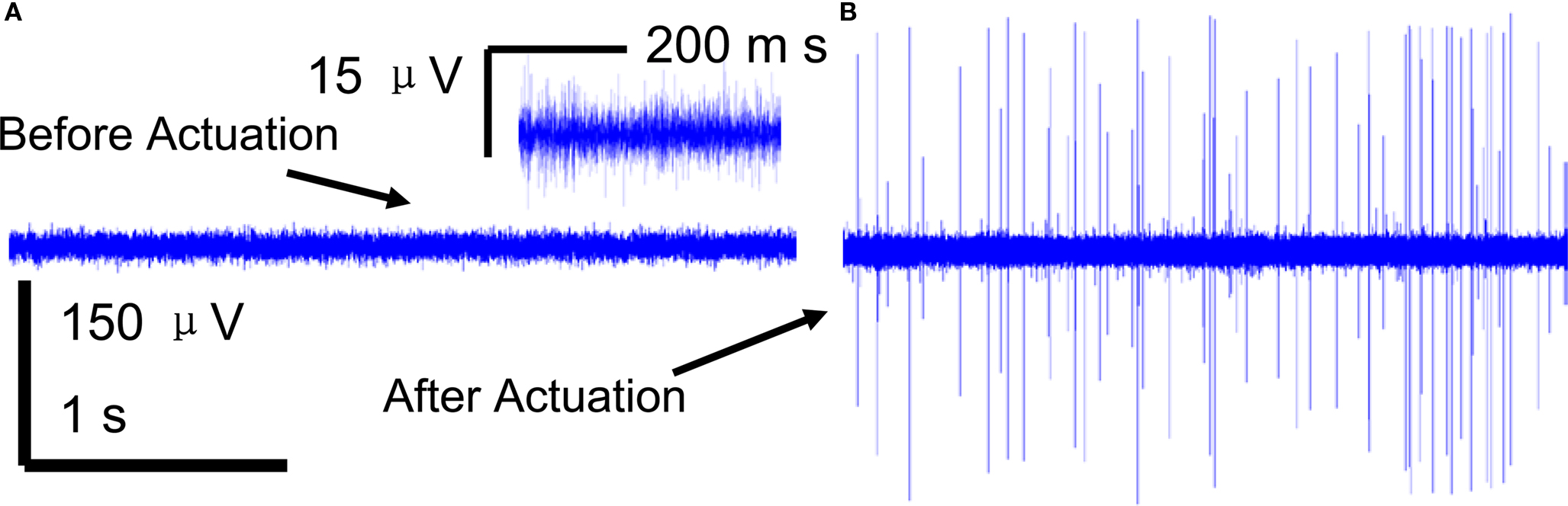
Figure 4. A 3-s snapshot of the raw neuronal multi-unit data recorded from a microelectrode (A) before movement (B) after movement. Insert in (A) shows a closer view of the noise with low signal levels that represents SNR < 10 dB SNR.
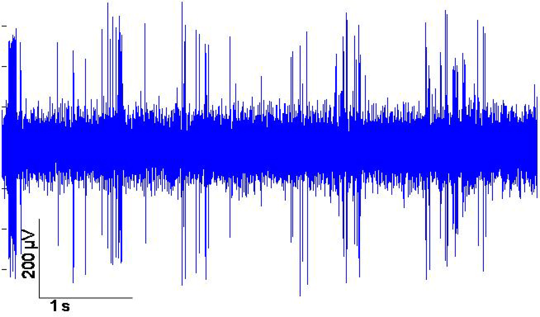
Figure 5. Example of neuronal multi-unit data recorded from the movable microelectrodes 83 days after implantation.
For the first 21-days post-implantation, the spike amplitudes ranged from 30–400 μV with typical noise values of 3-μV RMS. The average SNR of each of the microelectrodes before and after actuation over the first 21-days post-implantation is shown in Figure 6 A. If the SNR of the spike activity was larger than 10 dB, the microelectrodes were not actuated, and the corresponding recorded data was labeled “before actuation.” During the same period, the overall average SNR was 14.61 ± 5.21 dB before actuation and 18.13 ± 4.99 dB after actuation. Microelectrode movement consistently led to significant improvements in SNR values from each device shown in Figure 6 A. For instance, in Figure 6 A on the bottom left hand side of the graph shows that at day 1, 4, 8, and 21 the microelectrode was obtaining signals without actuation. However, on the other days (6, 12, 14, 16, and 18) the SNR was too low to distinguish between signal and noise so the microelectrodes were moved resulting in significant increase in the SNR. The 10 microelectrodes in the eight mesh-encapsulated devices were moved 43 times for the first 21 days and resulted in a significant improvement in SNR in 41 of those cases.
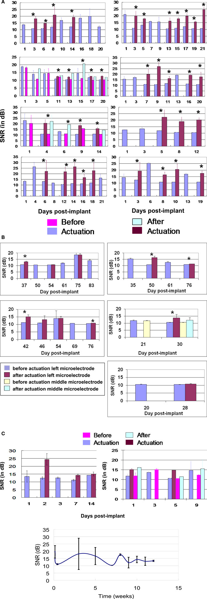
Figure 6. (A) SNR (dB) versus days post-implant for all 8 movable microelectrode devices (10 movable microelectrodes in total) for the first 21-days post-implantation. For each device the SNR of the neuronal recordings before and after each actuation is shown and indicated by an asterisk “*” above the bars to represent a significant difference. The second and third panels of the left column correspond to devices which had two movable microelectrodes. In the second panel from the top of the left column, there were two instances (days 11 and 17) when only one of two microelectrodes showed significant improvement in the SNR after movement. If no actuation was performed on a given day the corresponding recorded data is labeled “before actuation”. The error bars represent the standard deviation in the SNR. (B) SNR (dB) versus days post implant for all the microelectrodes that were functional beyond 3 weeks. For each device the SNR of the neuronal recordings before and after actuation is shown. If no actuation was performed on a given day the corresponding recorded data is labeled “before actuation”. The error bars represent the standard deviation of the SNR. In 6 out of 11 instances microelectrode movement led to significant improvement in the recorded SNR (indicated by an asterisk “*” above the bars). (C) SNR (dB) versus days post implant for two movable microelectrode chips which did not have the encapsulation but where the microelectrodes were moved in response to low SNR. (D) SNR (dB) versus days post implant over ∼12 weeks for the two control microelectrode chips which did not have the encapsulation and where the microelectrodes were kept stationary.
Five out of the eight devices survived beyond 3 weeks of implant duration. The SNR values from these remaining functional devices are shown in Figure 6 B. The average SNR for all functioning microelectrodes across the devices beyond 3 weeks of implant time was 11.88 ± 2.02 dB before actuation and was significantly different from 13.34 ± 0.919 dB after actuation (p < 0.01). In Figure 6 B, there were 6 out of 11 instances when movement of the microelectrode led to significant improvements in SNR. The improvement in SNR values (1–5 dB) was however lower compared to the improvements observed in the first 3 weeks.
In the two devices that were not encapsulated where the microelectrodes were actuated, the average improvement in SNR was ∼ 3–5 dB as shown in Figure 6 C. The average SNR over the 12 weeks for the control microelectrodes which were not moved are shown in Figure 6 D. The results show that the SNR was low during the first couple of weeks, then increased at week 3, and remained above 12 dB after the third week.
There was no significant difference (p > 0.10) in the average RMS values of noise before (2.98 ± 1.22 μV) and after actuation (3.01 ± 1.16 μV) in the first 3-weeks post-implant as shown in Figure 7 .
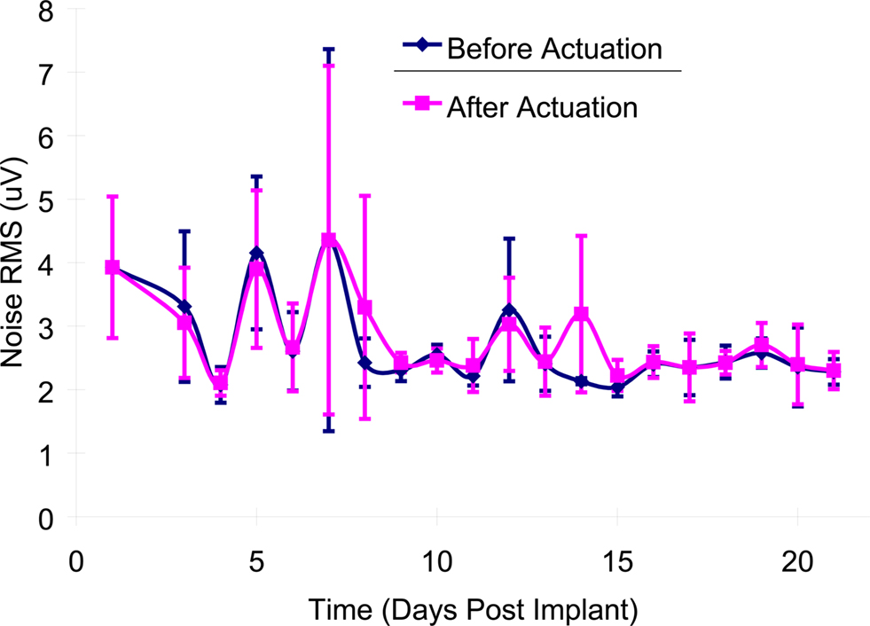
Figure 7. Mean noise levels (RMS) before and after microelectrode movement across all of the implanted microelectrodes over the first 21-days post-implantation. The error bars represent the standard deviation among all of the recordings for that particular day.
Impedance Measurements
A typical bode plot of the electro-chemical impedance spectra is shown in Figure 8 , which shows the impedance magnitude and phase change versus frequency (100 Hz–100 kHz). The average magnitude of the impedance trend at 1 kHz was monitored over the duration of the experiment (Figure 9 ). The average magnitude at 1 kHz during the first 3 weeks of the experiment was 341 ± 161 kΩ.
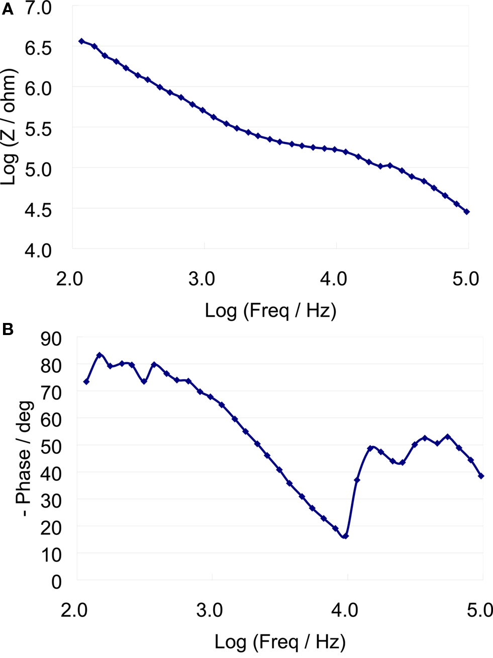
Figure 8. Eelectro-chemical Iimpedance spectrum of a typical microelectrode (A) impedance magnitude versus frequency (B) Impedance phase versus frequency.
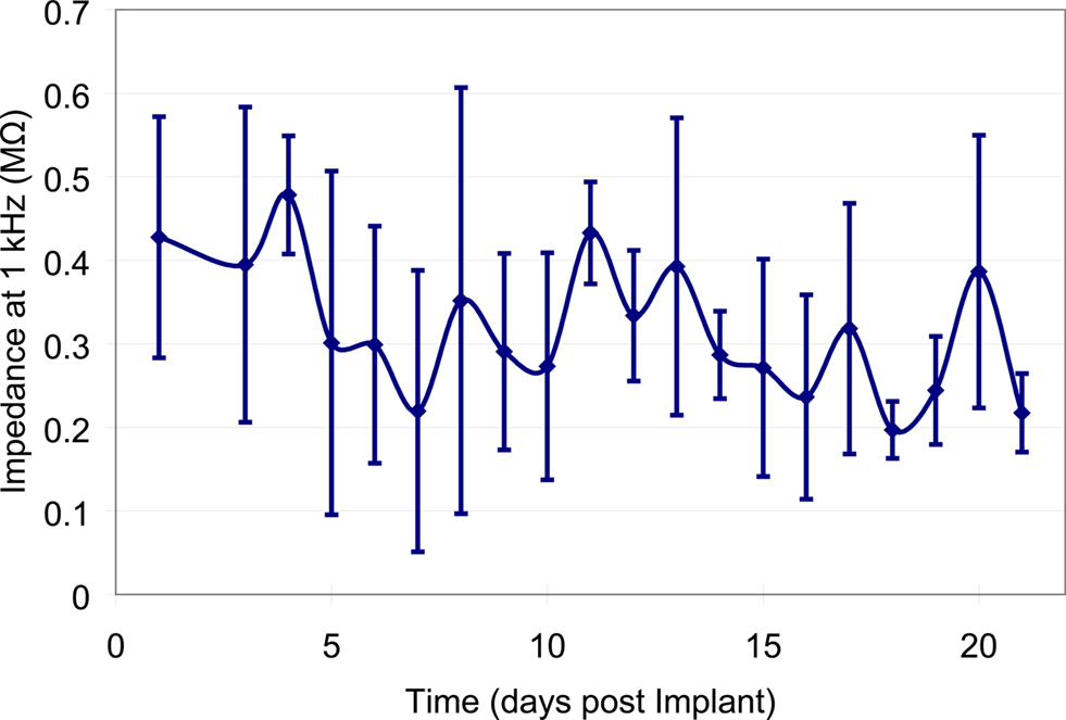
Figure 9. Mean impedance values at 1 kHz across all of the implanted microelectrodes over the first 21-days post-implantation. Error bars represent the standard deviation of the impedance amongst all of the microelectrodes for that particular day.
Discussion
This study validates the ability to use our MEMS based movable microelectrodes for semi-chronic neural recordings in the cerebral cortex. Single and multi-unit signals were obtained for six of eight devices for at least 28 days. Of these devices, three devices were able to obtain neural recordings for at least 76 days (∼11 weeks). In one device, active neural recordings were obtained for up to 83 days (device #2) suggesting the potential use of these devices in long-term Neurophysiological experiments. Recordings beyond 83 days had to be terminated due to unrelated health issues (dehydration and adverse reactions to the anesthetic injection site) of the rat implanted with device #2. During the first 3 weeks the SNR before and after actuation were significantly different (p < 0.01) with values of 14.61 ± 5.21 dB and 18.13 ± 4.99 dB respectively. The devices that went beyond 3 weeks showed a smaller but still significant increase in SNR before and after actuation with values of 11.88 ± 2.02 dB and 13.34 ± 0.919 dB respectively.
The ability to maintain SNR above 10 dB in all the devices that were tested demonstrates the ability to achieve a certain level of recording consistency by moving the microelectrodes intermittently unlike fixed microelectrodes where wide variations are observed in the recording quality both within an individual microelectrode over time and across different microelectrodes in different experiments. Recent studies have suggested variations in spike signal amplitudes within a 24-hr duration (Ryu and Shenoy, 2009 ) using fixed microelectrode arrays. A tightly designed closed-loop control system that adjusts the position of the movable microelectrodes featured here in response to any change in the SNR will potentially lead to not only maintaining a minimum SNR (as demonstrated here) but a stable SNR that does not fluctuate. Such control algorithms have already been successfully demonstrated in short-term experiments using bulky motors to move the microelectrodes (Cham et al., 2005 ) to achieve stable SNR values.
We used a criterion that a SNR of 10 dB would be undesirable since the spike amplitude is indistinguishable from the surrounding noise amplitudes. However, at an SNR of 12 dB or higher, the units were visually discernible and were of a quality that conventional detection and sorting algorithms such as what we have used in this study were able to detect and sort them. Therefore, in order to make an assessment of relevance for cortical prosthetic applications, neuronal recordings with SNRs 12 dB or higher that were discernible by conventional detection and sorting algorithms can be considered useful and hence relevant. This would make neuronal recording corresponding to every single data point in Figure 6 A after microelectrode movement useful for cortical prosthetic application. In Figure 6 B, only a subset (four out of the six) of the neuronal recordings corresponding to the six instances that showed significant improvement would actually be useful for cortical prosthetic application.
It is possible that microelectrode movement of 100 μm used here in response to SNR dropping below 10 dB could lead to drifts in relative position of the neuron and the microelectrode. However, we attempted to minimize the possibility of such drifts by moving the microelectrode very slowly at a rate of approximately 9 μm/s. The decrease in SNR of many of the recordings beyond 3-weeks post-implant is not unusual and might be a result of the isolation of the microelectrode from active neurons due to gliosis in the tissue surrounding the implant. The active neurons near the microelectrode may also have migrated away. Beyond 3 weeks, in 5 out of 11 cases, microelectrode movement does not lead to significant improvement in the SNR values. This might indicate that the electro-thermal microactuators are not as effective in moving the microelectrodes past the glial sheath that typically envelops the implants after 4 weeks. If that is the case, designing microactuators with greater force capabilities would enable the microelectrodes to penetrate and move past the glial sheath more effectively. The current actuators can produce forces of around several hundred micro-Newtons. It is also possible that it is more difficult to find viable neurons in the vicinity of the microelectrode tips beyond 3 weeks. This would have to be confirmed by sampling the brain space more carefully at higher spatial resolution.
The packaging techniques used, allowed for six out of eight (∼75%) encapsulated MEMS devices to be capable of moving the microelectrodes and recording multi-unit data from them throughout the duration of the experiment. Two of the devices without the mesh encapsulation (device 9 and 10) showed fluid entry at day 9 and 14 respectively. The other eight electrodes remained functional (movable) for at least 28 days. Only one implanted device had total device failure (device 4). Device 4 also had a connector problem 21-days post-implant due to debris entering the connector, which made it difficult to make secure connections with the headstage thus increasing the noise levels. Additionally, all the actuators and recording springs were catastrophically broken 49 days post-implantation in device 4. The likely cause for this mechanical failure in device 4 is yet unknown.
Device 1 had a little fluid entry on day 14, which prevented movement afterwards. However, we were still able to maintain functional neural recordings from Device 1 for four more days. Device 3 had fluid penetration 89-days post-implantation. A primary reason for this failure was due to the poor packaging of the device. It is speculated that the ion-rich biological fluid may be the primary reason for affecting device function. Nevertheless, this failure mode was observed in only two of eight implanted devices with encapsulation, suggesting that further refinements in the encapsulation method may help completely prevent failure due to fluid entry in future studies. While the microactuators themselves can function in fluids, the failure appears to result from solid debris left behind after dehydration of the fluid that had entered. Results from the two control experiments demonstrate viable neuronal recordings for approximately 3 weeks, suggesting fluid accumulation does not catastrophically affect the recording ability of the microelectrodes but does impair its mobility.
The primary failure mode beyond 3 weeks was the rejection of device due to significant tissue ingrowth on the skull under the dental cement. The tissue penetration resulted in partial degradation of the PMMA based dental cement, weakening the structural stability of the implanted device on the skull. The stresses exhibited by the tissue on the device-skull interface were strong enough to separate the mounted bone screws with the PMMA from the skull. The maximum lifespan of the PMMA/dental cement mounting technique without additional maintenance is ∼3–6 months. The primary reason for this mounting failure may be caused by the chronic irritation of the skin at the dental cement skin interface. Continual maintenance of the implant site by removal of any tissue ingrowths would be required in future experiments. Alternatives might be to utilize an adhesive to prevent tissue growth and to practice improved surgical techniques to prevent general chronic inflammation.
The packaging techniques used in this study are not ideal for chronic recordings, considering the relatively large size and weight of the chip carriers and underlying PC boards. In addition lack of mechanical isolation between the OmneticsTM connector and the implanted device increases the likelihood of failure due to recurrent mechanical stresses during insertion of connectors for recording. Although these movable microelectrodes are smaller than any other currently used movable microelectrodes for neural recordings, further work is necessary to optimize the form factor and weight for chronic experimentation. We have recently developed novel flexible MEMS techniques that reduces the size of the interconnects and packaging to chip-scale size (∼3 mm × 6 mm) and reduces the total weight to ∼250 mg (Jackson and Muthuswamy, 2009 ). This new packaging needs to be tested for chronic recordings in future studies. The MEMS based devices can be scaled up to increase the number of electrodes, and the weight would not be significantly altered. This can be accomplished through die thinning and advanced packaging and interconnect techniques (Jackson and Muthuswamy, 2009 ). Using such techniques the distance between the microelectrodes can be reduced from the current 800 μm to 400 μm or less and a 3-D array of movable microelectrodes that can precisely sample x-, y- and the z- directions in the brain tissue can be accomplished.
The results of this study show that microelectrode movement always led to a significant (p < 0.01) improvement in SNR in the first 3-weeks post-implant and in 6 out of 11 instances beyond 3-weeks post-implant. In a typical application, the microelectrodes may not need to be moved as often as was done in this study. We had used an ad-hoc approach in this study to move the microelectrode in response to any decrease in the SNR below 10 dB. However, it is possible that neurons that were active in the previous recording session may become silent (due to a variety of reasons such as sedation levels, behavior etc) in the subsequent recording session. On such occasions, even keeping the microelectrode stationary and waiting-out the silent periods in a neuronal activity may restore the SNR. However, the strategy based solely on waiting-out the silent periods for the restoration of SNR is ineffective in the long-term as demonstrated by fixed microelectrode arrays in use currently. The goal of this paper was to validate that the microelectrodes can move and obtain high SNR when there are no signals being obtained in their current position.
The increase in signal levels subsequent to microelectrode movement is most likely caused by the ability of the microelectrodes to move closer to a functional neuron. The noise levels (RMS) did not significantly (p > 0.10) change before and after movement. The RMS of the noise was 2.98 and 3.01 μV before and after movement respectively. Since the direction of movement was randomized, both upward and downward of the microelectrodes appear to be equally effective in improving the SNR values of the neuronal recordings.
The results from the impedance data show that the average impedance at 1-kHz on the first day after the implant was 427 ± 145 kΩ, while the average over the first 3 weeks was 341 ± 161 kΩ. This showed a marginal decrease of ∼85 kΩ. The decrease in the impedance occurs within the first couple of days, which is most likely caused from thin sections of the insulation layer that was not properly etched away. After day 5, the impedance values became more stable with marginal increases and decreases from day to day recordings. The large variations in impedance values from one sample to another are likely due to lack of control over the amount of insulation that is etched away, or the thickness of the insulation layer. The Bode phase plot of Figure 8 shows a capacitive behavior for the microelectrodes at low frequencies. It is speculated that there may have been a gradual increase in the surface area of the recording site due to the presence of proteins and other biological factors leading to an overall decrease in impedance.
Finally, one of the major challenges to overcome with these MEMS devices is their packaging. Typically MEMS devices are hermetically sealed in order to prevent fluid or debris from entering the movable components. However, hermetic packaging is not feasible for the above devices since the microelectrodes extend off the edge of the chip. We have recently developed a novel packaging technique in order to prevent fluid entry and still allow our microelectrodes to move or function normally after implantation (Jackson and Muthuswamy, 2009 ; Jackson et al., 2009 ).
Conclusions
We tested the ability to use MEMS based movable microelectrodes to record long-term neural activity in the cerebral cortex of adult rodents. This is the first study, to our knowledge that used MEMS based actuators to move microelectrodes post-implantation in long-term experiments. A couple of the devices failed due to leakage issues in the packaging. Future work will be directed towards improving the packaging and tethering of the MEMS device on the skull in order to obtain chronic recordings.
We conclude that movable microelectrodes using MEMS actuators is a promising approach to help increase the SNR of neuronal recordings in long-term experiments. Optimization of the packaging and surgical mounting will likely lead to successful neuronal recordings lasting several years from cortical regions of the brain.
Conflict of Interest Statement
The authors declare that the research was conducted in the absence of any commercial or financial relationships that could be construed as a potential conflict of interest.
Acknowledgment
Research supported by NIH research grant R01NS055312.
References
Cham, J., Branchaud, E., Nenadic, Z., Greger, B., Anderson, R., and Burdick, J. (2005). Semi-chronic motorized microdrive and control algorithm for autonomously isolating and maintaining optimal extracellular action potentials. J. Neurophysiol. 93, 570–579.
Fee, M. S., and Leonardo, A. (2001). Miniature motorized microdrive and commutator system for chronic neural recording in small animals. J. Neurosci. Methods 112, 83–94.
Jackson, A., and Fetz, E. (2007). Compact movable microwire array for long-term chronic unit recording in cerebral cortex of primates. J. Neurophysiol. 98, 3109–3118.
Jackson, N., Anand, S., Okandan, M., and Muthuswamy, J. (2009). Non-hermetic encapsulation materials for mems based moveable microelectrodes for long-term implantation in the brain. J. Microelectromech. Syst. 18, 1234–1245.
Jackson, N., and Muthuswamy, J. (2009). Flexible chip scale package and interconnect for implantable mems moveable microelectrodes for the brain. J. Microelectromech. Syst. 18, 396–404.
Muthuswamy, J., Okandan, M., Gilletti, A., Baker, M., and Jain, T. (2005a). An array of microactuated microelectrodes for monitoring single-neuronal activity in rodents. IEEE Trans. Biomed. Eng. 52, 1470–1477.
Muthuswamy, J., Okandan, M., Jain, T., and Gilletti, A. (2005b). Electrostatic microactuators for precise positioning of neural microelectrodes. IEEE Trans. Biomed. Eng. 52, 1748–1755.
Park, S., Yoon, E., Lee, S., Shin, H., Park, H., Kim, B., Kim, D., Park, J., and Park, S. (2008). The development of a PZT-based microdrive for neural signal recording. Smart Mater. Struct. 17, 1–7.
Reitboeck, H. J. (1983). A 19-channel matrix drive with individually controllable fiber micro-electrodes for neurophysiological applications. IEEE Trans. Syst. Man. Cybern.113, 626–683.
Ryu, S. I., and Shenoy, K. V. (2009). Human cortical prostheses: lost in translation? Neurosurg. Focus 27, E5.
Sato, T., Suzuki, T., and Mabuchi, K. (2007). A new multi-electrode array design for chronic neural recordings, with independent and automatic hydraulic positioning. J. Neurosci. Methods 160, 45–51.
Sniegowski, J. J., and de Boer, M. P. (2000). IC-compatible polysilicon surface micromachining. Annu. Rev. Mater. Sci. 30, 299–333.
Venkateswaran, R., Boldt, C., Parthasarathy, J., Ziaie, B., Erdman, A., and Redish, A. (2005). A motorized microdrive for recording of neural ensembles in awake behaving rats. J. Biomech. Eng. 127, 1035–1040.
Verhagen, J., Gabbott, P., and Rolls, E. (2003). A simple method for reconditioning epoxy-coated microelectrodes for extracellular single neuron recording. J. Neurosci. Methods 15, 215–217.
Weiland, J., and Anderson, D. (2000). Chronic neural stimulation with thin-film iridium oxide electrodes. IEEE Trans. Biomed. Eng. 47, 911–918.
Wilson, M., and McNaughton, B. (1993). Dynamics of the hippocampal ensemble code for space. Science 261, 1055–1058.
Keywords: neural prosthesis, neural prostheses, polysilicon, chronic brain implant, neuronal recordings, neural interface, brain machine interface, single unit activity
Citation: Jackson N, Sridharan A, Anand S, Baker M, Okandan M and Muthuswamy J (2010) Long-term neural recordings using MEMS based movable microelectrodes in the brain. Front. Neuroeng. 3:10. doi: 10.3389/fneng.2010.00010
Received: 24 December 2009;
Paper pending published: 21 January 2010;
Accepted: 27 May 2010;
Published online: 18 June 2010
Edited by:
Martin Stelzle, University of Tübingen, GermanyReviewed by:
Jun Yamamoto, Massachusetts Institute of Technology, USACopyright: © 2010 Jackson, Sridharan, Anand, Baker, Okandan and Muthuswamy. This is an open-access article subject to an exclusive license agreement between the authors and the Frontiers Research Foundation, which permits unrestricted use, distribution, and reproduction in any medium, provided the original authors and source are credited.
*Correspondence: Jit Muthuswamy, Bioengineering, ECG 334, P.O. Box 879709, Arizona State University, Tempe, AZ 85287-9709, USA. e-mail: jit@asu.edu