Soft-Legged Wheel-Based Robot with Terrestrial Locomotion Abilities
 Ali Sadeghi
 Alessio Mondini
 Emanuela Del Dottore
 Anand Kumar Mishra
 Barbara Mazzolai
- 1Center for Micro-BioRobotics, Istituto Italiano di Technologia, Pontedera, Italy
- 2The BioRobotics Institute, Scuola Superiore Sant’Anna, Pontedera, Italy
In recent years, robotics has been influenced by a new approach, soft-robotics, bringing the idea that safe interaction with user and more adaptation to the environment can be achieved by exploiting easily deformable materials and flexible components in the structure of robots. In 2016, the soft-robotics community has promoted a new robotics challenge, named RoboSoft Grand Challenge, with the aim of bringing together different opinions on the usefulness and applicability of softness and compliancy in robotics. In this paper, we describe the design and implementation of a terrestrial robot based on two soft-legged wheels. The tasks predefined by the challenge were set as targets in the robot design, which finally succeeded to accomplish all the tasks. The wheels of the robot can passively climb over stairs and adapt to slippery grounds using two soft legs embedded in their structure. The soft legs, fabricated by integration of soft and rigid materials and mounted on the circumference of a conventional wheel, succeed to enhance its functionality and easily adapt to unknown grounds. The robot has a semi-stiff tail that helps in the stabilization and climbing of stairs. An active wheel is embedded at the extremity of the tail in order to increase the robot maneuverability in narrow environments. Moreover, two parallelogram linkages let the robot to reconfigure and shrink its size allowing entering inside gates smaller than its initial dimensions.
Introduction
Terrestrial locomotion has been since long a topic of research for enhancing the development of autonomous systems in uneven environments for instance for mines detection (Hirose and Kato, 1998; Nonami et al., 2003), rescue operations (Murphy, 2004), and exploration of hostile environments (Bellingham and Rajan, 2007).
In terrestrial locomotion, wheels excel on prepared surface such as rails and roads but they fail in unstructured environments where instead legged locomotion can overcome unexpected obstacles and rough terrains (Raibert, 1986). In recent years, some works have been conducted to promote hybrid solutions between legs and wheels (Hong et al., 2009; Kim et al., 2014; She et al., 2015), or alternating terrestrial to aerial locomotion (Bachmann et al., 2009; Kalantari and Spenko, 2013). Also, a rough terrain is the cause of an unstable locomotion. For enhancing stabilization, it has been proposed, for example, the use of a tail (Chang-Siu et al., 2011). The tail can be helpful not only for providing stability but also for the actuation of rapid and precise turns of the robot (Chang-Siu et al., 2011; Kohut et al., 2013). In recent years, the emergent soft-robotics community has started to provide some novel ideas for solving common problems by providing compliancy in the structure of the robot for its dynamic adaptation (Godage et al., 2012; Kim et al., 2013; Majidi, 2014). In fact, through the employment of soft and compliant materials, it is possible to realize a novel set of robots, called soft robots, able to automatically change their structure, size, and functionalities for a dynamic adaptation to real environments. These peculiar characteristics are indeed particularly fundamental in disaster areas, where size and dimensions of steps and gates are unknown. Some examples of adaptation in terrestrial applications can be observed in the work done by Lee et al. (2013) where they propose an origami-based design for the wheels, providing the ability to lowered their size for passing gates or increasing their size for passing high steps; same capability has been previously provided to a terrestrial robot in the work of Koh et al. (2012) switching over three types of motion (wheel, caterpillar-like, and legged-wheel motion) by combining motor to a SMA coil actuator. Rone and Ben-Tzvi (2014) proposed a continuum hybrid actuated tail structure (tendon and rod driving mechanisms) able to generate forces in the x-, y- and z-directions for improving stabilization in locomotion in presence of external disturbances. Another example of soft robot is presented in Walker et al. (2012). Here, the authors proposed a soft, adaptable, and compliant continuum robot using hooks for its anchorage in low-gravity environments and McKibben air muscles for the continuum arm usable either as arm manipulator or legged locomotion mechanism. All of these mentioned examples successfully demonstrate the potential capability of soft robots in providing large deformations and easy adaptation to changing conditions, useful for different cases, such as safe interaction with users or working in unstructured and unknown environments.
The robot presented in this paper was developed to participate in the RoboSoft Grand Challenge, 2016, organized by the RoboSoft-Coordination Action for Soft Robotics (FP7-ICT-2013-C project # 619319). This was the first edition of an international robot challenge promoted by the SoftRobotics community with the aim of collecting different ideas on what soft-robotics means and where it is going, by proposing specific problematics to be faced by robots. In particular, terrestrial robots were asked to face a scenario emulating an urban area not accessible by humans.
During the challenge, we could observe a variety of solutions, some of them completely soft and based on silicone rubbers, others oriented to a more classical rigid robotics. In our work, we proposed a novel design for a wheel-leg-based locomotion exploiting a soft-solution approach in particular for improving the climbing of stairs and passing slippery grounds in a passive manner. This aim was obtained by employing a combination of hard and soft components in the design of the wheel, allowing the change of stiffness for a better adaptation to different conditions. Our robot is also able to change the overall dimension by reconfiguring the distance among the wheels. A multi-gait approach for the locomotion in different situations is also proposed, which can take advantage of an actuated tail with variable stiffness, particularly useful for passing stairs and for fine tuning the robot direction.
Design Criteria
Four different tasks were expected to be performed during the competition: (I) passing a sandy terrain, (II) passing through a gate, (III) passing stairs, and (IV) avoiding obstacles. Moreover, for tasks II and IV, the robots were required to pass in spaces smaller than the nominal robot dimension (Figure 1).
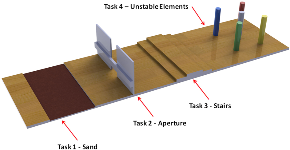
Figure 1. The tasks defined by the Grand Challenge for the terrestrial race: to start with a sandy ground, followed by a gate, then with three steps of stairs and finish with obstacles of unstable elements.
The robot has been designed to accomplish the proposed tasks following the very open and general guidelines provided by the Committee: robot should have a maximum dimension of 60 cm × 60 cm × 60 cm with a maximum weight of 20 kg, and it has been developed following “trial and testing” methodology, passing from prototyping to testing face for correcting the design until success. All the tasks can be easily overcome with classical robots, in particular using wheeled robots: simply choosing wheels with big diameter is possible to overcome the stairs (5 cm per step) without any problems. However, to meet the spirit of the event, we exploited soft robotic technologies for finding solution at the proposed tasks, and we decided to realize a robot smaller than the dimension of the competition field infrastructures in order to really face those tasks as a challenge: we arbitrarily chose a height less than the stair step and a length much shorter than the sandbank. Another feature we considered in the design is the autonomy of the robot; we intended in fact to propose a solution able to negotiate with all the problematics and go forward in the way without wired constrains and with its own power autonomy. These characteristics forced us to consider small embeddable actuation mechanisms with low power consumption. Also, the entire scenario needed to be completed in a maximum of 20 min, and in case of parity between teams the completion time becomes important: the fastest the winner. For this reason, we choose a wheel-based robot which can easily accomplish task I and can ensure the speed in all other tasks. For tasks II and IV, the key feature required by the competition is the shrinking capability. In order to accomplish these tasks, we employed a cable-driven actuation mechanism to reconfigure the distance between wheels. However, in the configuration with the wheels closed, we noticed high instability in wheels rotation, behavior that we corrected by implementing different locomotion gaits and introducing a tail embedding a wheel at its far end for tuning the robot direction. For passing stairs, because of our reduced size, we decided to employ a mixed solution, demonstrated to be successful from literature, by adding soft legs. An alternative to soft legs could be inflatable wheels, solution widely used among the other participants, but that would require miniaturized air pumps to be embeddable or an external air-supplier, which would go against our idea of robot autonomy; also such solution requires time for inflating and deflating, which we wanted to eliminate. Instead, legs in our design can partially increase the diameter of the wheels while the employment of softness here allows preserving small dimension for passing through small gates without compromising speed and locomotion for the other tasks.
Materials and Methods
As results of our reasoning and testing, we obtained a wheel-leg-based mobile robot with two main driving wheels that move the robot forward when they have the same velocity and orientation, and also change the robot orientation when they rotate with different velocities. The robot shows three main features: a reconfigurable body, soft-legged enhanced wheels, and a tail with multi-functionalities.
Reconfigurable Body
The body of the robot is composed by two arms and a flexible tail. It stays regularly in the format of a “T,” but “T,” or “Y” shapes can be assumed (Figure 2A). Two main wheels are located at the end of the arms as well as the flexible tail hosts a small active wheel which assists the robot in changing its direction, particularly in backward movements. Functionalities of tail are discussed in Section “Tail.”
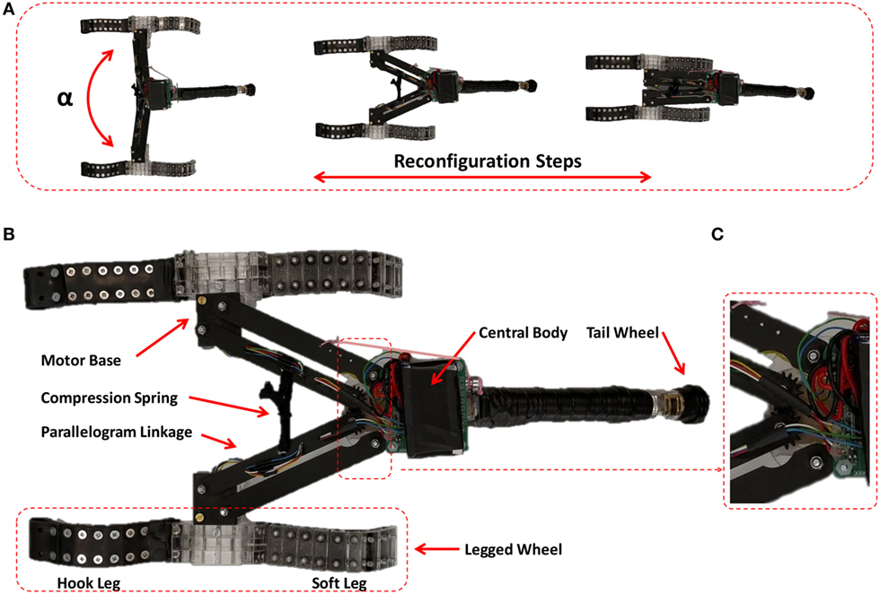
Figure 2. (A) Robot can reconfigure from a T to Y shape and vice versa. (B) Top view of the robot with wheels equipped with soft legs. (C) Close view of gear-coupling of left and right parallelogram linkages.
The body is constructed by a central part where a battery and a control unit are located (Figure 2B). Left and right arms and tail are separated modules assembled to the central part by means of two parallelogram linkages (Figures 2B,C). Due to these linkages, each arm (left and right) can have a planar motion parallel to the surface of the central part. These planar motions permit the body to transform and shrink its configuration from “T” to “Y” shape: if we define α as the angle between two arms, in our robot, α can vary from 180° to 0° (Figure 2A). Two links of the left and right arms are endowed with spur gears coupled together (Figure 2C) that guarantee to preserve a symmetric shape of the robot during transformation. The opening of arms is actuated by a cable-driven mechanism located in the central part. The closing process is passively actuated by the pulling force of an extension spring mounted between the two arms, which occur when the pulley/motor releases the cable. The parallelogram linkage is used to ensure the coaxiality of wheels in all the steps of reconfiguration, which is necessary for an accurate control and the effective motion of the robot. The re-configurability provided by this mechanism has allowed our robot to pass the gate (task II of the challenge) and to overcome obstacles (task IV of the challenge) positioned at a distance smaller than the robot predefined size.
Soft-Legged Enhanced Wheels
The wheels used in our mobile robot do not follow the circular shape of conventional wheels. The proposed wheel has two sides with two different properties for passively climbing the stairs and passing sandy and slippery grounds. Each wheel is an assembly of three main parts: one central quadrilateral part and two flexible legs that are installed to the sides of the central part (Figure 3A). Each leg is a flexible belt that on one side hosts a series of rigid cubic segments. These segments provide rigid constrains for reducing bending on one side of the belt, while, from the other side, it is free to bend with almost any desired curvature (Figure 3B). In the center of each cubic segment is present a through hole parallel to the surfaces of the belt and wheel. The holes can be used to pass a cable through all segments, and by putting the cable on a certain tension it is possible to generate in each leg a desired shape and stiffness (Figure 3B). By using legs with different stiffness properties, we can provide two different types of behaviors in the same wheel. The leg under tension gives a hook shape to one side of the wheel (Figures 3C,D). This configuration, due to the flexibility of semi-stiff hook, helps to adapt to the subject of climbing and prevents sliding downward; also, its geometrical shape partially increases the diameter of wheel, helpful property for overcoming stairs height. Instead, the leg installed on the other side of the wheel lacks the cable under tension and it is free to bend. Lack of cable permits this leg to continuously lean under the quadrilateral part of wheel when it is rolling on the ground (Figures 3E,G). The soft leg, that always in advance touches the ground, becomes an interface between wheel and ground. This interface somehow simulates the unrolling of a carpet in front of the wheel or the advancing of a track wheel. Instead of having a punctual contact point as in the normal wheel, here the contact with terrain is a wide surface fixed to the ground. Therefore, wheels can roll toward forward direction independently to the quality of the ground. Moreover, the rigid segments of the soft leg can work as teeth, improving frictional interaction between wheel and slippery ground.
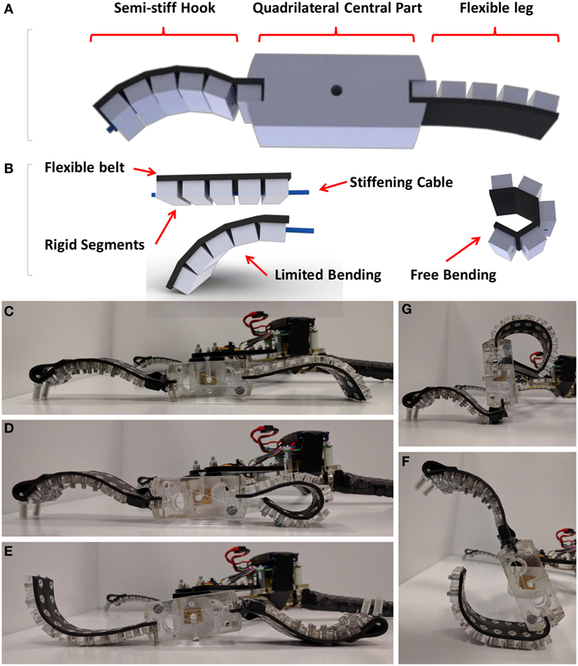
Figure 3. (A) CAD model of the wheel with two legs in the sides. (B) CAD model of flexible legs made of a flexible belt and rigid segments; the bending of belt is limited by the rigid segments from one side. From the other side, it can bend freely or its bending can be controlled by means of a cable. (C) Normal position of fabricated wheel on the ground. (D) The soft leg can bend with any radius. (E) The soft leg advances than wheel can touch the ground. (F) Wheel can role on the soft leg independently to the ground properties. (G) The bending of semi-stiff leg is limited and can function as a hook for climbing over obstacles.
Tail
Whereas two main wheels provide two contact points to the ground, the tail provides a third contact point necessary for robot stabilization, and by letting the active wheels rotate respect to the ground, forward motion is generated. The role of a tail in rapid maneuvers of robots, dynamic stabilization, and overcoming obstacles is presented in previous works (Chang-Siu et al., 2011; Kohut et al., 2013). In addition to give the capability of mobility, the tail can also help in stairs climbing (task III of the challenge): the longer the tail and more easily and stably the robot climbs stairs. However, it is important to note the maximum height the robot can climb is mainly a function of wheel frictional properties and maximum diameter; the tail functions only as a supportive structure. Increase in the tail length means increases the total length of robot, which can limit the robot in flexibility and passing through dedicated obstacles (task IV of the challenge). Therefore, a compromise is required between climbing a desired height and limiting the robot to pass through obstacles in order to select the proper final length.
The tail of our robot is constructed by a series of rigid and soft segments. Each segment has four holes, one in the center and three out of the center, used for passing cables for tuning a desired stiffness. An extendable rubber tube passes through the central holes of all segments to assemble them and to provide an axial compression force that sticks all the segments together. Also inextensible cables passes on the other holes in order to limit the bending orientation of the tail. The tension provided by the wires, together with compression tension of the axial flexible tubes, can define the stiffness of the tail. A tail almost rigid helps the robot to climb the stairs by using its stiffness, while its partial flexibility permits us to perform a crawling motion (used for backward locomotion). The central flexible tube is also used to pass the electrical wires of a small DC motor to drive a wheel mounted at the end of the tail (Figure 4A). This wheel can be used as a steering mechanism assistive for the wheels in both forward and backward motions (Video S1 in Supplementary Material).
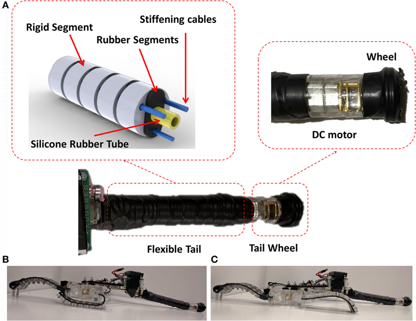
Figure 4. (A) Flexible tail constructed by rigid segments and flexible segments with an active wheel at the end. (B) Configuration of the wheels in backward crawling. (C) Configuration of the wheels in forward crawling.
Generation of backward motion in two-wheeled mobile robots is not always easy as classic wheeled vehicles with four or three wheels, which can move backward just by reversing the orientation of both driving wheels. As usual, the center of mass in two-wheeled robots is very close to the axis of active wheels, and it is very probable that robot somersaults when wheels rotate with an inverse direction. This can cause problems for robots (like ours), which do not have a symmetrical side view and their upside is different from their down side. Flexibility of the tail and structure of the wheels permit us to generate an alternating pattern for achieving a crawling function in our robot. Depending to the configuration of the wheels in contact with the ground (Figures 4B,C), it would be possible to generate the crawling motion in both forward and backward directions. Due to the fact that during the crawling a complete cycle of the wheels is not required, the robot in crawling mode has a smaller height respect to the one in locomotion obtained by rolling wheels. Adding this feature to the shrinking capability obtained by parallelogram linkages, our robot can pass a gate smaller in height as well as in width (we used both features for passing step II of the challenge).
Fabrication and Control
All the components of the robot were made using a laser cutting process (VERSALASER-VLS3.5), and they were assembled manually. The body was made by Delrin and Plexiglas. In particular, the gear-coupled links were made by Delrin that after laser cut has an acceptable quality and demonstrates a good resistance as gear. All the joints of the parallelogram linkages were realized simply by M4 screws and locknuts in order to prevent loosening of the nuts during the cyclic motions (Figure 2C). Each robot arm has 100 mm length, while the distance between the left and right wheels is 260 mm when the arms are totally open (180°). The duty of compression spring was done by a peace of waistband elastic. All the rigid components of wheels were fabricated by Plexiglas. Each resulted quadrilateral parts was a cube of Plexiglas with 60 mm × 25 mm × 24 mm. The flexible belt was fabricated out of polychloroprene rubber sheet with 2 mm thickness, and all the rigid segments were mounted on its surface by screws. The resulted assembly was a belt with surface of 80 mm × 24 mm and 7 mm thickness after mounting the rigid segments (Figures 3C–G). For the pulling cable that passes through the holes of segments, we used a fishing wire with a diameter of 0.35 mm. Each driving wheel was directly mounted on the shaft of a DC gear motor (Pololu Inc., 3079, gear ratio 298:1, 6 V), located at the end of the arms in a box of Plexiglas called motor base. The side view of each wheel could fit inside a rectangle with 240 mm length and 25 mm height. The wheel demonstrates two radiuses varying from 120 to 12.5 mm: one useful to pass narrow gates and the other useful for climbing the obstacles. The maximum radius of 120 mm was achieved by the assembly of semi-stiff hook (Figure 3C). The rigid segment of the tail was fabricated by Plexiglas of 8 mm, while the soft segments were the same material of the legs (polychloroprene rubber sheet of 2 mm). A tube of silicone rubber (VERSILIC 3 mm × 5 mm) was used as axial extendable tube, while for pulling cables was used a fishing wire with a diameter of 0.35 mm. The tail after assembled to the robot was a cylinder with a diameter of 20 mm and length 170 mm (Figure 4A). The DC gear motor used in the tail was the same used for the active wheels. The control unit and battery were mounted on the central part of the body. The robot is fully untethered and driven by a user through a custom-developed Android App. A controller board was designed to manage the four motors of the robot and to have a Bluetooth link with the App. This board is composed by a microcontroller (PIC32MX150F128B from Microchip Inc.), a Bluetooth module (RN42 from Microchip Inc.), an inertial module able to supply acceleration and magnetic field on three axes (LSM9DS0 from STMicroelectronics), and eight motor drivers (LV8548MC from ON Semiconductor). The wheels were equipped with two magnetic encoders (Magnetic Encoder Pair Kit for Micro Metal Gearmotors from Pololu Inc.) installed on the shaft of the motors in order to permit position or speed control (Figure 5).
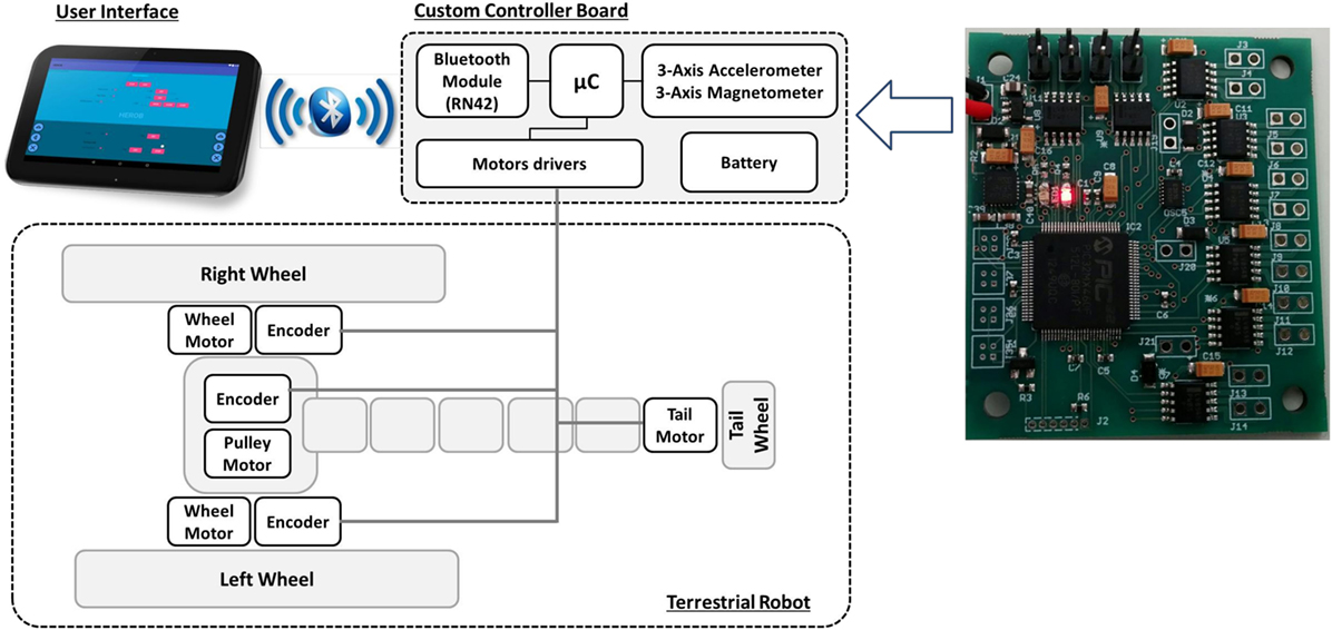
Figure 5. The architecture of control unit.
Several modes can be used to drive the robot during locomotion, which are as follows:
Mode 1: the wheels maintain the same relative position; in particular the legs of the two wheels are aligned, which is useful for climbing stairs. In this mode, when turning is necessary, a wheel is stopped and the other rotates with complete numbers of turns and then the stopped one restarts aligned with the other.
Mode 2: the wheels are free to move (even with desynchronized legs), and the wheel speed is kept with a closed loop control. Turning is achievable by setting different speeds to the wheels. The direction can be maintained both by direct control of an operator or a closed loop control on the robot direction given by the magnetometer. This mode is useful to pass sand and avoid obstacles with high turning precision.
Mode 3: the crawling mode. In this modality, controls on position and speed are removed. The wheels are in this case driven with an alternate oscillating pattern. This oscillation is characterized by a period and an intensity of the power given to the motors; by varying these two parameters with the user interface is possible to obtain different oscillation patterns and to select the best combination for adapting the motion to the current surface. This mode is used to pass the small gate of task II.
Experiments and Results
The developed robot is able to perform three types of motions: forward by active wheels (used for long distances locomotion and climbing the stairs) (Figures 6A–F) and forward- and backward-oriented crawling. All these motions were tested on two different types of ground materials: woven cotton and Delrin. Cotton could provide good frictional properties while Delrin was as example of slippery grounds.
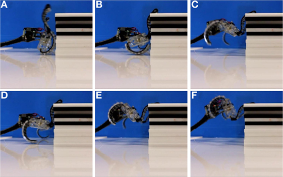
Figure 6. (A–F) Sequential images of hook leg during interaction with stair and climbing.
Active Wheel Locomotion and Climbing
The tests of forward locomotion for both cotton and Delrin grounds were performed with different setting angles of ground surface (0°, 3°, 6°, 9°, 12°, and 15°). The linear velocity of the robot was recorded in 10 trials when the velocity of wheels was set at 30 rpm. The results of these experiments are plotted in (Figure 7A). As it was expected, the performance of the robot on the cotton surface was better than on the slippery Delrin. The maximum speeds of the robot were recorded when the ground was horizontal, obtaining 209 mm/s for textile and 173 mm/s for Delrin. The robot succeeded to climb the slope of a cotton ground up to 12°, but it could not climb a slope of 15°. Instead, in the case of Delrin, the maximum angle found was 9°. For climbing the stairs, we performed the experiment covering the steps with both selected grounds. These tests were repeated 20 times for each step height. We obtained that the maximum heights the robot could climb were 140 mm on stairs covered by cotton (85% tests were successful) and 120 mm in stairs covered by Delrin (75% tests were successful) (Figures 6A–F).
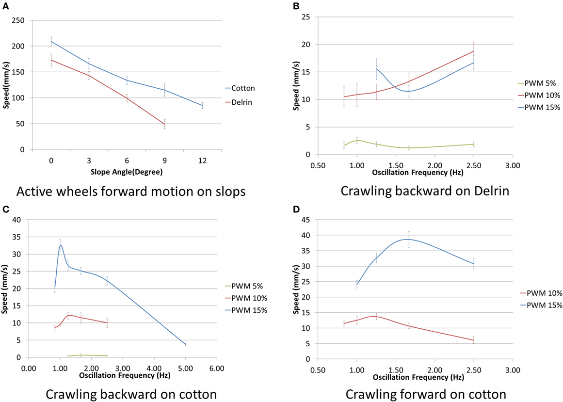
Figure 7. (A) Velocity of the robot in forward locomotion on cotton and Delrin with different angles. (B–D) The resulted speed of crawling on cotton and Delrin with different oscillation frequencies and power intensities.
Crawling and Passing the Gate
We succeeded to generate crawling motion in both forward and backward directions either changing the configuration of wheels and type of wheel–ground contact. Each wheel was set to alternately repeat a cycle of clockwise and counter clockwise partial rotations. The velocity of the robot in both forward and backward orientations on cotton and Delrin was recorded with different oscillation frequency (1.25–5 Hz) and power intensity (5, 10, and 15% PWM) in five trials for each configuration. The results of these experiments are plotted in Figures 7B–D. On Delrin, the robot performed backward crawling but was not able to perform forward crawling, while it succeeded on both backward and forward orientations on the cotton. The crawling was a complex result of dynamic frictional interaction of contact points in the wheel and tail with ground. The maximum crawling velocity of 38.46 mm/s was achieved for forward crawling on the cotton when the PWM was set at 15% and frequency of wheel oscillation was 1.67 Hz; while this maximum on Delrin was 17.24 mm/s with oscillation frequency of 2.5 Hz and 10% of PWM. The capability of crawling together with shrinking allowed our robot to reduce to almost 54% its initial size (240 mm × 140 mm) and pass a gate with a minimum size of 140 mm × 60 mm.
Discussions and Lessons from the Challenge
We proposed a wheel-leg-based mobile robot with the capability of climbing stairs taller than the robot wheel diameter and passing slippery grounds, like sand, in a passive manner. The wheels of the robot can reconfigure on stairs and not slide on slippery grounds due to a sort of soft legs that are added radially to the wheel circumference. The particular design of the legs fabricated by a combination of soft and rigid materials permits them to demonstrate two different ranges of flexibilities: one totally flexible used as interface for adaptation on the slippery grounds and the other semi-flexible used for adapting and hanging to the stairs (140 mm maximum height) in climbing applications. By employing parallelogram linkages, the robot has a reconfigurable structure that can shrink its width up to 54%. By exploiting the property of flexibility of the components, in the wheel and tail design, we succeed to generate a crawling motion in addition to the normal forward locomotion. The proposed robot participated in the RoboSoft Grand Challenge, 2016 (Figure 8). The competition took place within a day, preceded by 1 day of testing on the arena where teams could test their robot on each tasks once. Guidelines let teams very much free to propose any kind of solutions, and we could observe in fact a variety of robots. There were some robots basically made of silicon with external air pump actuation mechanisms or other inflatable soft materials for enlarging or reducing their dimension or more rigid-based robots employing for instance origami strategy in the wheels (Kim et al., 2014). Also, there was a lot of variety in the size, from really small robot (contained in one hand) to very large robots at the limit of size constrains. Winner of the terrestrial competition was a wheel-based robot that mixed rigid with soft technologies. In their case, size played a fundamental role, being bigger than step height allowed them to overcome sand and stairs easily and to be the fastest. In our case, during the challenge the flexible legs embedded in each wheel permitted our robot to easily and passively pass the sandy terrain. The robot succeeded in accomplishing task II of the terrain competition by passing a gate 31% smaller in width than its initial size due to its shrinking and crawling capabilities. Even if, in lab experiments, the robot was able to easily pass stair over 100 mm height, during the competition, accomplish this task was quite challenging. By observation during the first day of competition, we could rationalize two important facts (both related to the material of the flexible legs) affecting the behavior of the robot from the lab to the open field. First, the stickiness of the rubber during lab experiments helped the robot in climbing stairs, while the stickiness of the same material became a problem during the competition: it absorbed dust passing the sandy ground decreasing rapidly the frictional properties of the hook legs for a successful climbing. This problem could be mitigated by adding two nails at the tip of each hook leg to increase its hanging on the surface of stairs made by chipboard sheets. The second observation was the rapid aging of the selected rubber for the soft legs. The aging problem of soft materials can be faced by a proper selection of materials and fabrication process taking into account the working condition and the desired lifetime of the robot. Finally, task IV was completed by gaps 42% smaller than the initial robot size (Figure 8D). In this task, as well as for task II, the active wheel embedded at the end of the tail increased the maneuverability of the robot in passing narrow spaces between obstacles. Surprisingly, during the experiment of crawling locomotion, we observed several unpredictable behaviors caused by the flexibility of soft components. This experience led us to conclude that, by adequately exploiting such property in the design and control of robots, it would be possible to generate motion patterns that facilitate the adaptation to the environment and permit escaping from unpredicted stocking situations.
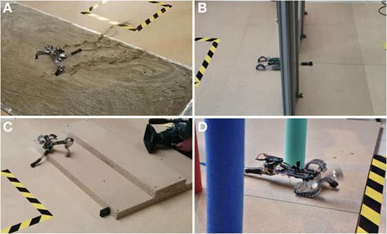
Figure 8. Robot during the RoboSoft competition: (A) task 1 – sand; (B) task 2 – aperture; (C) task 3 – stairs; (D) task 4 – unstable elements.
Author Contributions
AS – design, fabrication, experimentation, and writing. AM – design of controller, experimentation, and writing. ED – design of app for control and writing. AKM – design discussion, experimentation, and writing. BM – advising and writing.
Conflict of Interest Statement
The authors declare that the research was conducted in the absence of any commercial or financial relationships that could be construed as a potential conflict of interest.
The handling Editor declared a shared affiliation, though no other collaboration, with the authors ED and AM and states that the process nevertheless met the standards of a fair and objective review.
Supplementary Material
The Supplementary Material for this article can be found online at https://www.frontiersin.org/article/10.3389/frobt.2016.00073/full#supplementary-material.
Video S1. Robot locomotion in different modes: moving forward, backward crawling, passing stairs, etc.
References
Bachmann, R. J., Boria, F. J., Vaidyanathan, R., Ifju, P. G., and Quinn, R. D. (2009). A biologically inspired micro-vehicle capable of aerial and terrestrial locomotion. Mech. Mach. Theory 44, 513–526. doi:10.1016/j.mechmachtheory.2008.08.008
Bellingham, J. G., and Rajan, K. (2007). Robotics in remote and hostile environments. Science 318, 1098–1102. doi:10.1126/science.1146230
Chang-Siu, E., Libby, T., Tomizuka, M., and Full, R. J. (2011). “A lizard-inspired active tail enables rapid maneuvers and dynamic stabilization in a terrestrial robot,” in IEEE/RSJ International Conference on 2011 Intelligent Robots and Systems (San Francisco), 1887–1894.
Godage, I. S., Nanayakkara, T., and Caldwell, D. G. (2012). “Locomotion with continuum limbs,” in IEEE/RSJ International Conference on 2012 Intelligent Robots and Systems (Algarve: IEEE), 293–298.
Hirose, S., and Kato, K. (1998). “Development of quadruped walking robot with the mission of mine detection and removal-proposal of shape-feedback master-slave arm,” in IEEE International Conference on Robotics and Automation, 1998. Proceedings, Vol. 2 (Leuven: IEEE), 1713–1718.
Hong, D., Jeans, J. B., and Ren, P. (2009). “Experimental verification of the walking and turning gaits for a two-actuated spoke wheel robot,” in International Conference on 2009 IEEE/RSJ Intelligent Robots and Systems (St Louis), 402–403.
Kalantari, A., and Spenko, M. (2013). “Design and experimental validation of hytaq, a hybrid terrestrial and aerial quadrotor,” in IEEE International Conference on 2013 Robotics and Automation (ICRA) (Karlsruhe), 4445–4450.
Kim, S., Laschi, C., and Trimmer, B. (2013). Soft robotics: a bioinspired evolution in robotics. Trends Biotechnol. 31, 287–294. doi:10.1016/j.tibtech.2013.03.002
Kim, Y. S., Jung, G. P., Kim, H., Cho, K. J., and Chu, C. N. (2014). Wheel transformer: a wheel-leg hybrid robot with passive transformable wheels. IEEE Trans. Robot. 30, 1487–1498. doi:10.1109/TRO.2014.2365651
Koh, J. S., Lee, D. Y., Kim, S. W., and Cho, K. J. (2012). “Deformable soft wheel robot using hybrid actuation,” in IEEE/RSJ International Conference on 2012 Intelligent Robots and Systems (Algarve), 3869–3870.
Kohut, N. J., Pullin, A. O., Haldane, D. W., Zarrouk, D., and Fearing, R. S. (2013). “Precise dynamic turning of a 10 cm legged robot on a low friction surface using a tail,” in IEEE International Conference on 2013 Robotics and Automation (ICRA) (Karlsruhe), 3299–3306.
Lee, D. Y., Jung, G. P., Sin, M. K., Ahn, S. H., and Cho, K. J. (2013). “Deformable wheel robot based on origami structure,” in IEEE International Conference on 2013 Robotics and Automation (ICRA) (Karlsruhe), 5612–5617.
Majidi, C. (2014). Soft robotics: a perspective – current trends and prospects for the future. Soft Rob. 1, 5–11. doi:10.1089/soro.2013.0001
Murphy, R. R. (2004). Trial by fire [rescue robots]. IEEE Robot. Autom. Mag. 11, 50–61. doi:10.1109/MRA.2004.1337826
Nonami, K., Huang, Q., Komizo, D., Fukao, Y., Asai, Y., Shiraishi, Y., et al. (2003). Development and control of mine detection robot COMET-II and COMET-III. JSME Int. J Ser. C 46, 881–890. doi:10.1299/jsmec.46.881
RoboSoft Grand Challenge. (2016). FET-Open Scheme (FP7-ICT-2013-C project # 619319). Available at: http://www.robosoftca.eu/
Rone, W. S., and Ben-Tzvi, P. (2014). “Continuum robotic tail loading analysis for mobile robot stabilization and maneuvering,” in ASME 2014 International Design Engineering Technical Conferences and Computers and Information in Engineering Conference (pp. V05AT08A009-V05AT08A009) (Buffalo: American Society of Mechanical Engineers).
She, Y., Hurd, C. J., and Su, H. J. (2015). “A transformable wheel robot with a passive leg,” in IEEE/RSJ International Conference on 2015 Intelligent Robots and Systems (IROS) (Hamburg), 4165–4170.
Keywords: soft robot, terrestrial robot, transformable wheel, legged robot, mobile robot
Citation: Sadeghi A, Mondini A, Del Dottore E, Mishra AK and Mazzolai B (2016) Soft-Legged Wheel-Based Robot with Terrestrial Locomotion Abilities. Front. Robot. AI 3:73. doi: 10.3389/frobt.2016.00073
Received: 03 August 2016; Accepted: 14 November 2016;
Published: 02 December 2016
Edited by:
Marcello Calisti, Sant’Anna School of Advanced Studies, ItalyReviewed by:
Isuru S. Godage, Vanderbilt University, USASurya Girinatha Nurzaman, Monash University Malaysia Campus, Malaysia
Copyright: © 2016 Sadeghi, Mondini, Del Dottore, Mishra and Mazzolai. This is an open-access article distributed under the terms of the Creative Commons Attribution License (CC BY). The use, distribution or reproduction in other forums is permitted, provided the original author(s) or licensor are credited and that the original publication in this journal is cited, in accordance with accepted academic practice. No use, distribution or reproduction is permitted which does not comply with these terms.
*Correspondence: Ali Sadeghi, ali.sadeghi@iit.it